 2026-05-22
 Content
A gas spring looks deceptively simple — a pressurized cylinder with a sliding rod. But every surface that seals, guides, or bears load must be machined to exact specifications. Miss a bore diameter by even a few hundredths of a millimeter and nitrogen gas bleeds past the seals, the spring loses its rated force, and an OEM customer rejects the entire batch. Automotive gas spring CNC machining is therefore one of those processes where tolerances aren't negotiable, and every tool path decision has a downstream consequence on product life.
This article walks through the critical machining operations, materials, tolerance requirements, and surface finishing steps involved in manufacturing high-quality automotive gas spring components — whether you're quoting a production run or designing parts for manufacturability.
An automotive gas spring assembly contains several machined components, each with distinct function and dimensional criticality. Understanding what each part does makes it easier to specify the right process and tolerances from the start.
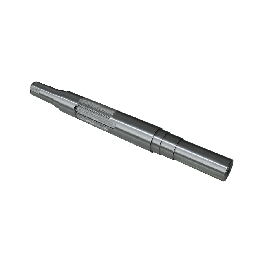
The cylinder is the outer housing — usually a seamless steel or aluminum tube that holds pressurized nitrogen. CNC operations here focus on bore finishing and end-face machining. The internal bore must be honed or finish-turned to achieve both the correct diameter and a surface roughness low enough for the piston seals to glide without excessive friction or wear. Internal diameters in automotive gas spring cylinders commonly range from 10 mm to 60 mm, with bore tolerances in the range of H7 (typically ±0.010–0.025 mm depending on diameter).
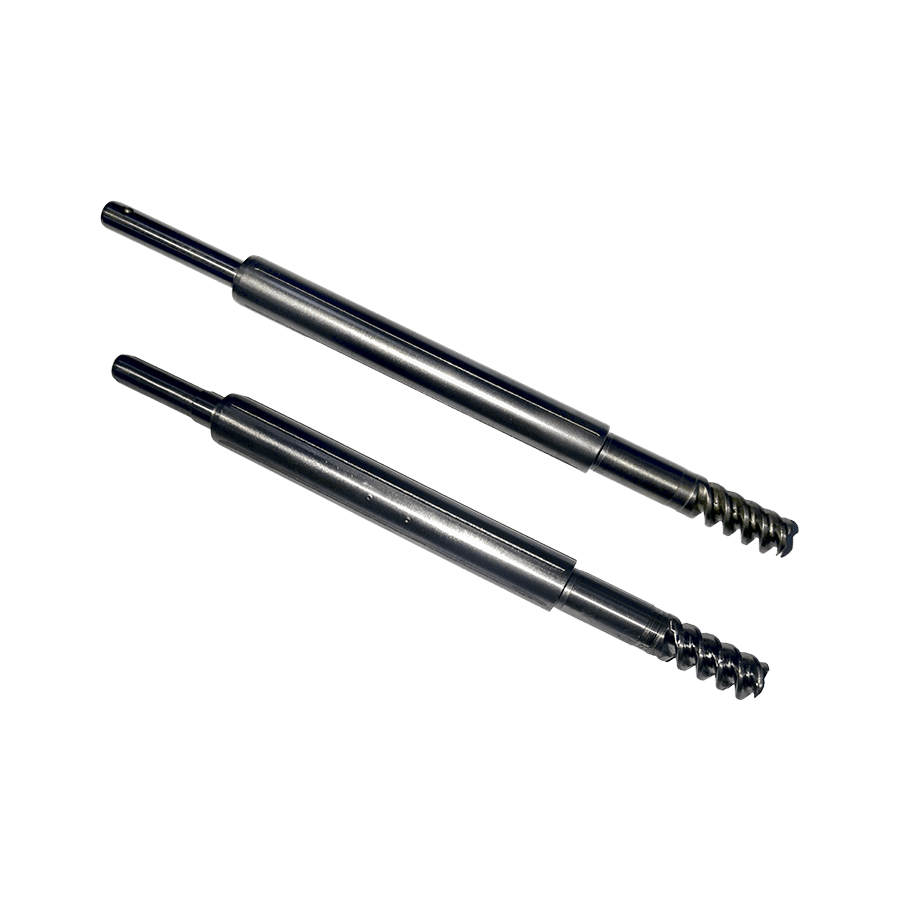
The piston rod is the most dimensionally critical single component. It must be straight to within tight limits, have a diameter held to close tolerances for seal fit, and carry a surface finish that resists both wear and corrosion. CNC turning produces the rod blank; subsequent centerless grinding and hard chrome plating or nitrocarburizing are standard post-machining steps. Rod diameters typically run from 6 mm to 28 mm in automotive applications, and straightness deviations beyond 0.05 mm over 300 mm of length can cause piston binding and accelerated seal failure.
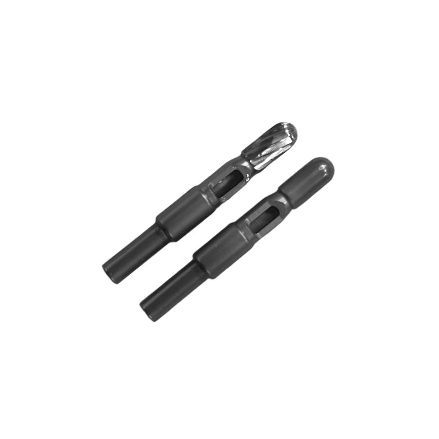
The piston itself is machined to fit the bore with a controlled clearance. It carries the gas-passage geometry — grooves, holes, or stepped profiles — that governs gas flow behavior during compression and extension. CNC turning and milling operations create these features. Any burr left in a gas passage or seal groove alters flow characteristics and risks seal damage during assembly.
The rod guide aligns and supports the piston rod at the open end of the cylinder. It requires a precisely bored ID to match the rod diameter and an OD to fit the cylinder bore without play. End caps for sealed designs are often crimped or threaded in place, so thread geometry and face-squareness matter for leak-free assembly. These parts are typically CNC-turned in steel or engineering plastics reinforced with metal inserts.
Material choice affects every downstream machining decision — cutting speeds, tool selection, surface finishing methods, and final inspection criteria. Automotive gas spring components are predominantly made from a small set of materials, each with known machining characteristics.
| Component | Typical Material | Key Machining Consideration |
|---|---|---|
| Cylinder tube | Cold-drawn seamless steel (e.g., ST52, E235) | Pre-drawn bore reduces internal machining; finish honing achieves final Ra |
| Piston rod | Case-hardened carbon steel (e.g., C45, 42CrMo4) | Hard chrome or nitriding after CNC turning; grinding to final diameter |
| Piston | Zinc die-cast, steel, or POM polymer | Die-cast parts need finish turning; polymer parts need low heat, sharp tools |
| Rod guide / end cap | Brass, aluminum, or steel | Brass machines freely; aluminum requires flood coolant for surface quality |
| Lightweight variants | Aluminum alloy (e.g., 6061-T6, 7075) | High feed rates possible; anodizing required for corrosion protection |
Steel remains the dominant choice for structural components due to its high tensile strength and well-understood fatigue behavior under cyclic gas pressure loads. Aluminum alloys are used more often in weight-sensitive passenger car applications — trunk lid struts are a typical example — where the lower operating pressure allows thinner wall sections and smaller rod diameters. For any aluminum gas spring component, anodizing or hard coating is mandatory to prevent fretting corrosion at the rod-seal interface.
Gas spring performance is directly governed by the dimensional relationship between the piston rod, the cylinder bore, and the sealing elements. Specifying tolerances too loosely risks leakage and short service life; specifying them tighter than necessary drives up machining cost without adding functional value. The table below summarizes practical tolerance targets for the key fit interfaces.
| Interface | Fit Type | Typical Tolerance (diameter) | Purpose |
|---|---|---|---|
| Piston rod OD / seal ID | Close running (f7/H7) | ±0.010–0.015 mm | Ensures seal contact without rod drag |
| Cylinder bore / piston OD | Clearance (H7/e8) | +0.020–0.060 mm clearance | Allows piston travel without metal contact |
| Rod guide OD / cylinder bore | Transition (H7/js6) | 0–0.015 mm | Prevents guide rocking; preserves rod alignment |
| Thread on end cap | 6H / 6g standard | ISO metric, medium fit | Sealing under pressure; ease of assembly |
For critical bore dimensions, CNC turning alone is rarely sufficient as the final operation. Honing adds the combination of dimensional accuracy and controlled surface lay that seals require — a turned bore at Ra 0.8 µm degrades seal life compared to a honed surface at Ra 0.2–0.4 µm. Piston rod diameters are similarly finish-ground after turning, with the grinding step holding the final h6 or f7 tolerance band needed for proper seal engagement.
Beyond diameter, gas spring components require control of form errors. A bore that is within diameter tolerance but significantly out-of-round will generate uneven seal compression, leading to localized leakage paths. Roundness requirements for cylinder bores in automotive gas spring production are typically 0.003–0.008 mm (3–8 µm), which is achievable with quality CNC turning followed by honing on a dedicated machine. Cylindricity — the combination of roundness and straightness over the full bore length — matters most for longer cylinders where thermal growth during machining can introduce barrel or taper errors.
Surface roughness values are specified as Ra (arithmetic mean roughness) and must be verified with a profilometer, not estimated by visual inspection. The cylinder bore and piston rod working surfaces each have distinct targets:
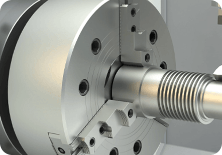
The cylindrical geometry of gas spring components makes CNC turning the dominant manufacturing process. Modern CNC turning centers — particularly twin-spindle, twin-turret machines — are well-suited to automotive gas spring production because they can complete a part in a single setup, eliminating the re-fixturing errors that degrade concentricity between the bore and outer diameter.
Piston rods are typically produced from bar stock on a CNC lathe with a bar feeder. The turning sequence includes rough OD turning, threading at the attachment end, undercutting for snap rings or seal grooves, and chamfering. Because bar stock is the starting material, straightness of the incoming material matters — bowed bar stock introduces runout that carries through to the finished rod and can only be corrected by centerless grinding. Specifying straightness of the raw bar to within 0.5 mm per meter before machining prevents rework downstream.
Gas spring components are high-volume products. Automotive OEM suppliers producing tens of thousands of cylinders per month need cycle times in the range of 30–90 seconds per part to be cost-competitive. Twin-turret CNC turning centers address this by machining two features simultaneously — for example, rough-turning the OD while finish-boring the ID — cutting cycle times by 30–50% compared to sequential operations on a single-turret machine. Lights-out operation overnight with automated bar feeding and part collection further reduces cost per piece for high-volume runs.
Some gas spring designs require radial ports, cross-drilled fill holes, or milled flats on the cylinder end for assembly tooling engagement. A CNC turning center with live tooling handles these features in the same setup as the turning operations, avoiding a secondary CNC milling operation. This is particularly important for gas fill ports — small-diameter holes drilled radially into the cylinder wall — where position accuracy relative to the bore centerline affects the sealing plug fit.
Raw CNC-machined surfaces are almost never the final surface condition for automotive gas spring components. Corrosion, wear, and friction performance requirements all drive post-machining treatments that must be accounted for in the original machined dimensions.
Hard chrome is the most common surface treatment for piston rods. A typical chrome layer of 10–25 µm is deposited after grinding, then ground again to the final diameter. This "plate and grind" sequence achieves both the surface hardness (900–1000 HV) needed to resist seal wear and the Ra 0.1 µm finish required for low-friction operation. Chrome adds to the rod diameter, so the pre-chrome ground diameter must be calculated to land within tolerance after the chrome deposit — a step that requires consistent plating process control and close communication between the machining shop and the plating facility.
For applications where chrome plating is restricted due to environmental regulations (hexavalent chrome is subject to REACH restrictions in Europe), nitrocarburizing — also called ferritic nitrocarburizing or Tenifer/Melonite treatment — is the preferred alternative. The process diffuses nitrogen and carbon into the steel surface to form a hard compound layer 10–20 µm thick, combined with a deeper diffusion zone that increases fatigue strength. Unlike chrome plating, nitrocarburizing produces minimal dimensional change (typically under 5 µm growth), so tight-tolerance rods can often be processed without a post-treatment grinding step. The resulting surface has excellent corrosion resistance and a characteristic dark gray appearance.
Cylinder bores receive honing after CNC turning to achieve the final diameter, roundness, and surface texture simultaneously. Plateau honing — a two-step honing process using a coarser stone followed by a fine finishing stone — produces a surface with shallow valleys for oil retention and flattened peaks that resist wear. This profile is measured by Rk parameters (core roughness depth, reduced peak height, reduced valley depth) rather than simple Ra values, and should be specified on drawings for critical bore applications. Plateau-honed bores extend seal life significantly compared to straight-turned or single-step honed surfaces.
Cylinder tubes and structural steel components that don't need a wear surface are typically zinc-nickel electroplated for corrosion protection. Zinc-nickel (12–15% nickel content) offers substantially better salt spray resistance than conventional zinc plating — typically 720–1000 hours to red rust in neutral salt spray testing versus 120–240 hours for zinc alone. For automotive exterior or underbody gas springs exposed to road salt and moisture, this corrosion performance is required by most OEM specifications.
Automotive gas spring machining operates under tight quality systems, typically IATF 16949 or ISO 9001 with automotive-specific customer requirements. Inspection is not a final gate — it's integrated into the production flow through statistical process control and in-process gauging.
Air gauging is the preferred method for high-volume diameter inspection because it is fast (measurement in under 2 seconds), non-contact, and highly repeatable. An air gauge spindle inserted into the bore or placed around a rod measures the air backpressure, which is directly correlated to the diameter via a calibration master. Air gauges are typically integrated into the CNC turning cell so every part is gauged before unloading, enabling real-time feedback to the machine tool's offset compensation system.
Coordinate Measuring Machine (CMM) inspection is used for first-article approval, periodic audits, and any features that air gauging cannot easily measure — including thread pitch diameter, perpendicularity of bore to face, and position of cross-drilled holes. CMM programs for gas spring components are typically written to match the drawing GD&T callouts, and the resulting measurement reports are submitted to the customer as part of the Production Part Approval Process (PPAP).
After assembly, 100% leak testing is standard practice for automotive gas springs. The most common method uses helium mass spectrometry or differential pressure decay testing. Differential pressure testing is more practical for high-volume production — the assembled spring is pressurized to a test pressure, isolated, and any pressure drop over a set period (typically 10–30 seconds) is compared against a reject threshold. A well-calibrated pressure decay test can reliably detect leak rates below 1 cc/min of nitrogen at working pressure.
Design engineers specifying automotive gas spring components can reduce machining cost significantly by following a few practical rules. These don't compromise function — they align the design with the natural capabilities of CNC turning and related processes.
 +86-13861233850