 2026-04-21
 Content
A precision motor shaft is the central rotating component of an electric motor — the cylindrical rod that transmits torque from the motor's rotor to the driven load. While that description sounds straightforward, the word "precision" carries enormous engineering weight. A precision motor shaft is not simply a turned steel rod; it is a carefully dimensioned, surface-finished, and tolerance-controlled component whose geometric accuracy directly determines how well the motor performs, how long it lasts, and whether the system it drives operates reliably.
In low-precision applications, shaft inaccuracies can be masked by flexible couplings or absorbed by compliant mounting systems. But in high-speed motors, servo drives, medical devices, aerospace actuators, and precision instrumentation, even micron-level deviations in shaft diameter, runout, or surface finish translate directly into vibration, bearing wear, power loss, noise, and premature failure. The gap between an ordinary motor shaft and a precision motor shaft is not just a matter of tighter numbers on a drawing — it reflects fundamentally different manufacturing processes, metrology practices, and material selection criteria.
This article covers everything engineers, procurement specialists, and product designers need to understand about precision motor shafts — from material selection and manufacturing methods to tolerance standards, surface treatment, and failure analysis.
Material selection is the foundation of precision motor shaft performance. The chosen material must satisfy multiple competing requirements simultaneously: sufficient strength to transmit rated torque without yielding, adequate hardness to resist surface wear at bearing and coupling interfaces, machinability that allows tight tolerances to be achieved economically, and in many cases, resistance to corrosion, temperature extremes, or magnetic interference.
Medium-carbon steels such as AISI 1045 and low-alloy steels like AISI 4140 and 4340 are the workhorses of precision motor shaft production. AISI 1045 offers a good balance of strength, toughness, and machinability in the normalized or quenched-and-tempered condition, making it suitable for general-purpose industrial motor shafts in the small-to-medium power range. AISI 4140 — a chromium-molybdenum alloy steel — provides significantly higher tensile strength, better fatigue resistance, and improved hardenability, making it the preferred choice for shafts subjected to combined bending and torsional loading in demanding industrial drives. AISI 4340 steps further up the strength ladder and is used where maximum core toughness alongside high surface hardness is required, such as in aerospace motor shafts and high-cycle servo applications.
Where corrosion resistance is a primary requirement — food processing equipment, marine motors, medical devices, chemical handling systems — stainless steel motor shafts are the standard solution. Grade 303 stainless steel offers good machinability but lower strength and corrosion resistance than other grades. Grade 316 provides superior corrosion resistance in chloride environments and is frequently specified for marine and chemical applications. Martensitic stainless steels such as 17-4 PH (precipitation-hardened) combine high strength with good corrosion resistance and can be hardened to demanding surface hardness requirements, making them a premium choice for high-performance precision shafts in corrosive environments.
Titanium alloys — particularly Ti-6Al-4V — are specified for precision motor shafts in aerospace, defense, and high-performance motorsport applications where weight reduction is a critical design driver. Titanium's strength-to-weight ratio is exceptional, and its natural corrosion resistance eliminates the need for surface coatings in most environments. The tradeoff is significantly higher material cost and more demanding machining requirements, as titanium's low thermal conductivity and tendency to work-harden require careful tool selection, conservative cutting parameters, and abundant coolant application during machining.
In motors used in MRI equipment, magnetic encoders, or precision scientific instruments, shaft material magnetic permeability must be minimized to prevent interference with the electromagnetic system. Austenitic stainless steels (such as 316L), certain aluminum alloys, and titanium alloys are all non-magnetic options used in these specialized precision motor shaft applications. Careful material certification and permeability testing are standard practice in these sectors.
Tolerance specification is what separates a precision motor shaft from a commodity turned part. Motor shafts interact with multiple mating components — bearings, couplings, gears, pulleys, seals, and rotor laminations — each of which imposes its own dimensional and geometric requirements on the shaft. Meeting all of these simultaneously, to micron-level accuracy, across the entire length of the shaft is the core challenge of precision shaft manufacturing.
Bearing seats are the most tolerance-critical zones on any precision motor shaft. Rolling element bearings require an interference fit on the shaft to prevent inner ring creep under load — but too much interference risks cracking the inner ring during assembly or generating excessive preload that reduces bearing life. ISO tolerance system fits such as k5, m5, and n5 (for light to heavy interference) are standard for bearing journal diameters, with actual diameter tolerances typically in the range of ±2.5 to ±8 micrometers depending on shaft diameter and bearing type. Achieving these tolerances consistently in production requires cylindrical grinding rather than turning alone.
Total indicated runout (TIR) — the total variation in shaft surface position relative to the true rotational axis — is perhaps the most critical geometric parameter on a precision motor shaft. Runout at the rotor mounting zone causes electromagnetic imbalance; runout at coupling interfaces causes vibration and coupling wear; runout at bearing journals causes dynamic loading that reduces bearing life exponentially. For high-speed motors above 3,000 RPM, shaft runout at the bearing journals is typically specified at 5 micrometers TIR or better. For precision servo motors and spindle motors, runout specifications of 1–2 micrometers are not unusual.
A shaft that is not straight will vibrate at rotational frequency regardless of how well it is balanced. Straightness tolerance on precision motor shafts — expressed as a maximum deviation from a perfect straight line over the full shaft length — is typically specified at 0.01 to 0.05mm per 300mm of shaft length for industrial motors, and 0.005mm or better for high-precision servo and spindle applications. Cylindricity — the combination of roundness, straightness, and taper of a cylindrical surface — is equally important at bearing journal zones where any out-of-round condition generates vibration at frequencies proportional to the number of roller elements per revolution.
Surface roughness at bearing journals is specified in Ra (arithmetic mean roughness) values, typically Ra 0.4 to Ra 0.8 µm for standard industrial motor shafts and Ra 0.1 to Ra 0.4 µm for precision servo and high-speed spindle motors. At seal contact zones, surface roughness must be within a narrow range — too rough and the seal lip wears prematurely; too smooth and the lubricant film breaks down. Most seal manufacturers specify a surface finish of Ra 0.2 to Ra 0.8 µm with a specific lay direction (circumferential rather than axial) at seal contact surfaces.
Achieving the tolerances described above requires a carefully sequenced manufacturing process in which each operation builds on the last and the thermal and mechanical state of the workpiece is managed throughout. A typical precision motor shaft manufacturing sequence involves multiple stages, each with a specific purpose.
Precision motor shaft production begins with verified bar stock or forging — material certifications confirming chemical composition, mechanical properties, and ultrasonic inspection results are standard in aerospace and medical applications. The initial turning operation on a CNC lathe removes the bulk of excess material, establishes the major diameter zones, and machines center holes at each end. These center holes are the datum reference for all subsequent grinding operations and must themselves be accurately positioned and formed — a damaged or eccentric center hole propagates geometric error through every downstream process.
For shafts requiring surface hardness at bearing journals or keyway zones — the majority of precision motor shafts — heat treatment follows rough turning. Through-hardening (quench and temper) improves core strength and toughness. Case hardening processes such as carburizing, carbonitriding, or induction hardening create a hard surface layer (typically 58–62 HRC) over a tough core, providing excellent wear resistance and fatigue life at critical interfaces without making the entire shaft brittle. Induction hardening is particularly common on precision motor shafts because it can be applied selectively to specific diameter zones with minimal distortion — though any heat treatment causes some shaft distortion that must be accounted for in subsequent grinding allowances.
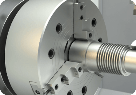
Cylindrical grinding — both between-centers and centerless — is the operation that achieves the final diameter tolerances, surface finish, and geometric accuracy on a precision motor shaft. Between-centers grinding, where the shaft is supported on its datum center holes and rotated against a grinding wheel, is preferred for achieving the tightest runout and concentricity specifications because all diameters are ground from a common datum. The grinding process removes only 0.05 to 0.3mm of material in carefully controlled passes, with wheel dressing, in-process gauging, and coolant management all contributing to achieving consistent results across a production batch.
After grinding establishes the primary diameters, secondary features — keyways, cross-holes, threaded end bores, splines, and flats — are machined using milling, broaching, or hobbing operations. The sequence matters: features cut after grinding avoid introducing the thermal and mechanical distortion that would require re-grinding, but they must be positioned accurately relative to the already-ground diameters. Keyway position tolerance relative to the shaft centerline is typically controlled to within ±0.05mm or better on precision motor shafts to ensure proper key and coupling alignment.
Precision motor shafts are 100% inspected against their drawing specifications before dispatch in most precision applications. Inspection methods include bench micrometer and air gauge measurement for diameter tolerances, CMM (coordinate measuring machine) measurement for geometric tolerances and feature positions, V-block and dial indicator runout checks, and surface profilometer measurement for Ra values. For aerospace and medical shafts, full dimensional reports with actual measurement values — not just pass/fail results — are required for traceability records.
Beyond the base material and machined geometry, surface treatments applied to precision motor shafts can significantly enhance their performance in specific operating environments. The right surface treatment extends shaft life, reduces friction, prevents corrosion, and in some cases enables the shaft to meet specifications that the base material alone cannot achieve.
| Treatment | Process | Key Benefit | Typical Application |
| Hard Chrome Plating | Electrodeposition of chromium | High surface hardness, wear and corrosion resistance | Hydraulic motors, marine drives |
| Electroless Nickel | Chemical nickel deposition | Uniform coating, corrosion resistance, moderate hardness | Food processing, chemical motors |
| Black Oxide | Chemical conversion coating | Mild corrosion resistance, reduces light reflection | General industrial motors |
| Nitrocarburizing (Ferritic) | Diffusion of N and C into surface | Hard compound layer, fatigue and wear resistance | High-cycle servo and traction motors |
| DLC Coating | Diamond-like carbon PVD/CVD | Extreme hardness, very low friction coefficient | Aerospace, high-speed precision spindles |
| Phosphating | Chemical phosphate conversion | Improves paint adhesion, mild corrosion protection | General purpose, storage protection |
One critical consideration with any surface coating on a precision motor shaft is dimensional impact. Hard chrome plating and electroless nickel add measurable thickness to the shaft surface — typically 0.005 to 0.05mm per side — which must be accounted for by grinding the shaft undersize before coating, then post-coating grinding or lapping to final dimensions. Diffusion treatments like nitrocarburizing and ferritic nitrocarburizing add minimal dimensional change (typically less than 0.002mm) and therefore do not usually require post-treatment grinding.
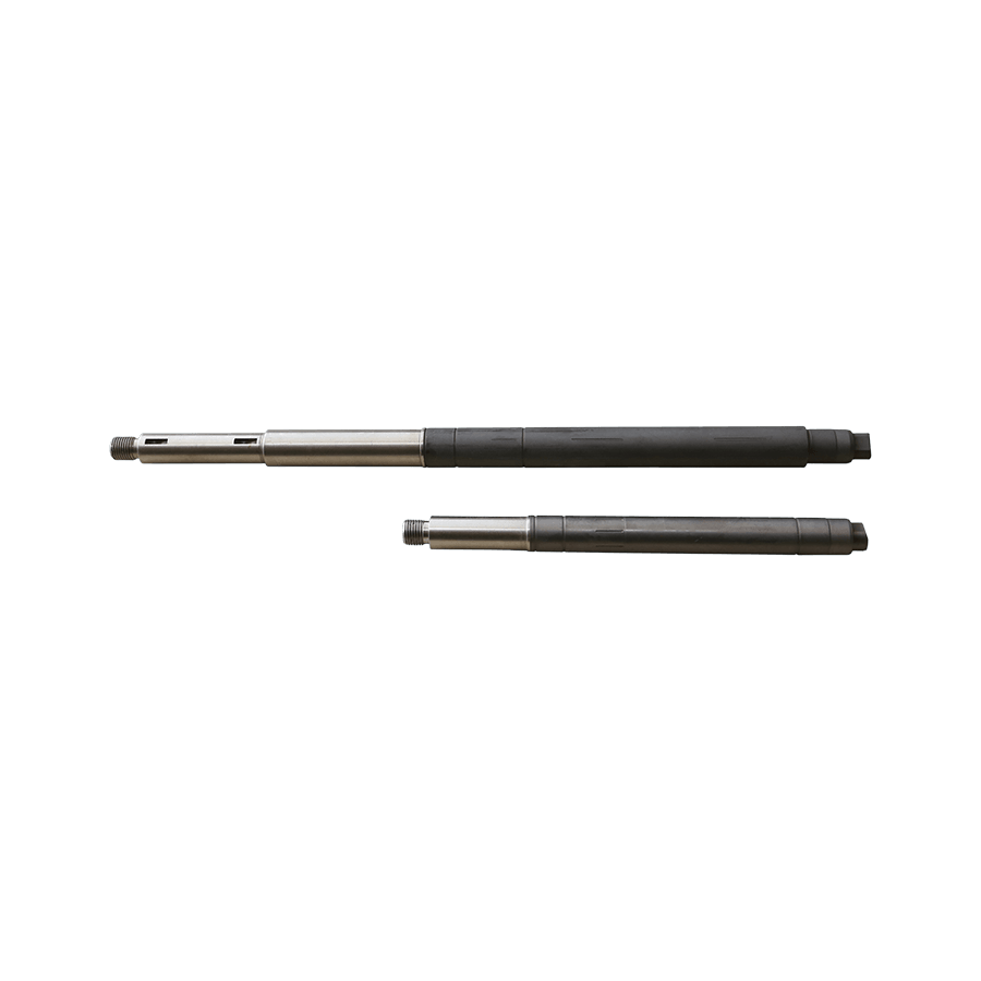
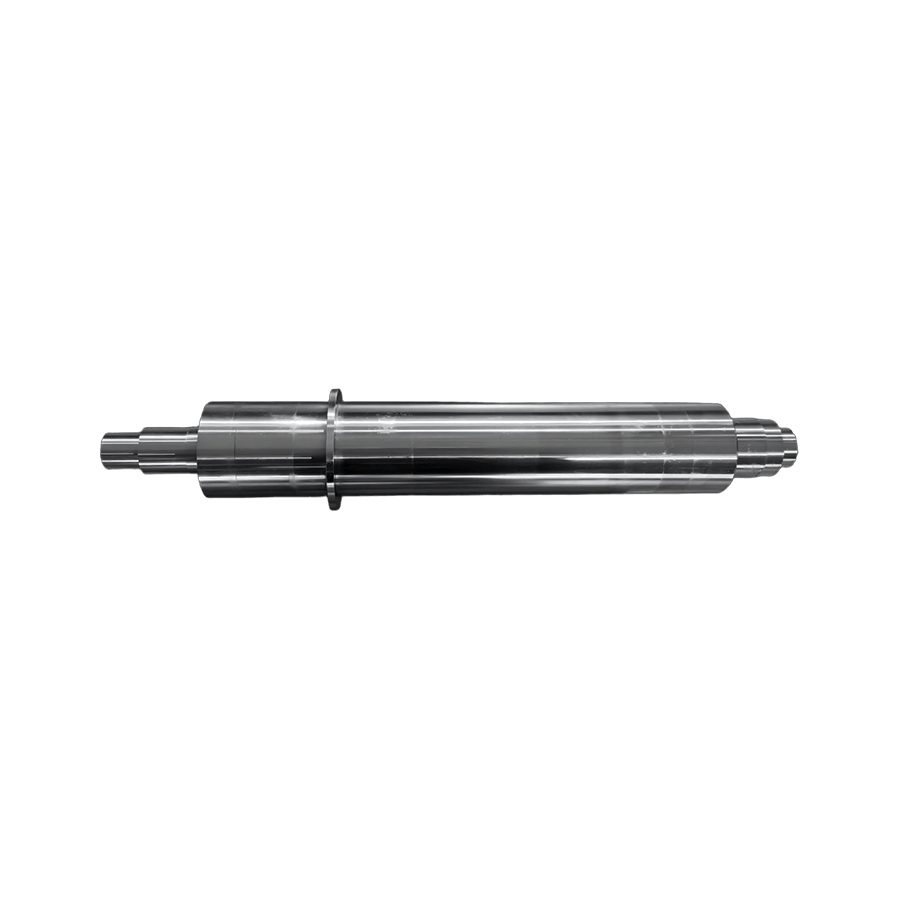
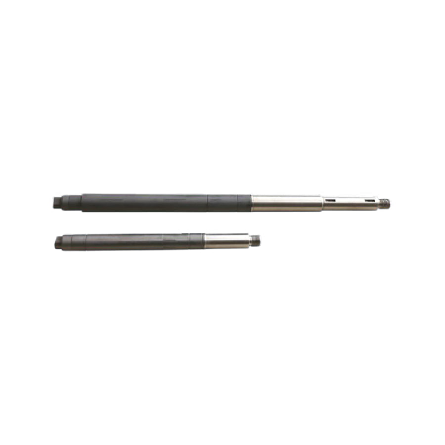
Precision motor shafts are not simple uniform cylinders. They incorporate a range of designed features that serve specific functional purposes and whose geometry must be carefully controlled during manufacturing.
Bearing journals are the shaft zones where rolling element or plain bearings are mounted. They are ground to precise diameter tolerances (typically h5, k5, or m5 ISO fits), specific surface roughness values, and tight cylindricity and runout specifications. Shoulders adjacent to bearing journals provide axial location for the bearing inner ring. The shoulder radius must be carefully controlled — too sharp a radius creates a stress concentration that initiates fatigue cracking; too large a radius prevents the bearing inner ring from seating fully against the shoulder face.
Keyways are rectangular slots machined into the shaft to accept a key that locks a gear, pulley, or coupling to the shaft for torque transmission. Keyway width and depth tolerances, position relative to the shaft centerline, and surface finish at the keyway flanks all affect the security and life of the key joint. Splines — essentially multiple keyways arranged around the shaft circumference — are used where higher torque transmission, self-centering, or slideable engagement is required. Involute splines are the most common form on precision motor shafts and are hobbed or ground to DIN or ANSI standard tooth profiles.
Many precision motor shafts incorporate threaded sections at one or both ends for nut-retained bearings, encoder mounting, or fan attachment. Thread quality — class of fit, pitch accuracy, and surface finish on the thread flanks — affects the clamping force achievable and the resistance to thread fatigue under vibration. For critical motor shaft applications, rolled threads (rather than cut threads) are preferred because rolling induces beneficial compressive residual stresses that significantly improve fatigue life at the thread root.
The drive end of a precision motor shaft — the section that protrudes from the motor housing and connects to the driven load — is typically manufactured to IEC or NEMA standard dimensions for interchangeability. The diameter tolerance, length, keyway geometry, and shaft end chamfer are all standardized, allowing motor shafts from different manufacturers to mate with the same coupling or gearbox input. Custom motor shaft extensions are also common in OEM applications where the standard shaft dimensions do not match the driven equipment's requirements.
Understanding how and why precision motor shafts fail is essential for both failure investigation and preventive design. Most shaft failures in service fall into a small number of recurring categories, each with identifiable root causes that can be addressed through design, material selection, or manufacturing process improvements.
Precision motor shafts are designed and manufactured against a range of industry standards that define dimensional requirements, material specifications, and quality practices. Familiarity with the relevant standards helps engineers specify shafts correctly and evaluate supplier compliance.
Sourcing precision motor shafts — whether as custom machined components or as replacement parts for existing motors — requires evaluating supplier capability against the specific requirements of your application. Not all precision shaft manufacturers are equal, and the lowest-cost option rarely delivers the dimensional consistency and traceability that demanding applications require.
Ask potential suppliers what grinding equipment they use, what their demonstrated process capability (Cpk values) is for bearing journal diameters at your specified tolerance, and whether they perform in-process gauging during grinding or only final inspection after completion. Suppliers using modern CNC cylindrical grinders with automatic in-process gauging and post-process SPC charting are significantly more capable of delivering consistent precision results than those relying on manual wheel-feed grinding with post-process measurement only.
Verify that the supplier has calibrated measurement equipment appropriate for the tolerances being inspected — air gauges or high-resolution bench micrometers for tight diameter tolerances, CMM capability for geometric tolerances and feature positions, and surface profilometers for roughness measurement. Calibration certificates traceable to national standards (NIST, PTB, NPL) should be available on request. For first article inspection or critical production batches, request a full dimensional report with actual measured values rather than a simple certificate of conformance.
For aerospace, medical, and safety-critical applications, every precision motor shaft must be traceable back to a specific material heat or lot number, with the corresponding mill certificate confirming chemical composition and mechanical properties. Ensure your supplier's quality system captures this traceability from incoming material receipt through to final inspection and dispatch records. Gaps in material traceability are a common finding in supplier audits and can result in costly quarantine and rework actions if discovered after parts are in service.
A supplier experienced in manufacturing precision motor shafts for servo drives understands the runout and surface finish requirements that those applications demand. A supplier specializing in large industrial motor shafts may have the right grinding capacity but lack experience with the tighter tolerances typical of servo applications. Request application-specific references, ask about their experience with the materials and heat treatment processes your shafts require, and if possible, request sample parts for first article inspection before committing to production volumes.
 +86-13861233850