 2025-11-18
 Content
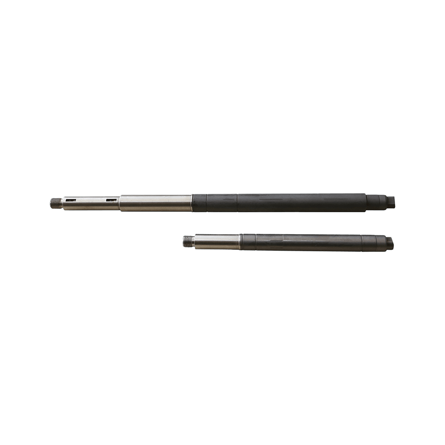
Choosing the right material for an electric motor shaft governs strength, fatigue life, machinability, corrosion resistance, and cost. Common shaft materials include AISI 1045 (medium carbon steel), 4140/4340 (alloy steels for higher strength), stainless grades like 304/316 for corrosive environments, and sometimes non-ferrous alloys (bronze or aluminum) for low-load or weight-sensitive applications. For high-speed or high-cycle applications, quenched and tempered alloy steels such as 4140 are often specified and surface-hardened to resist wear at bearing and seal interfaces.
The shaft diameter is chosen to satisfy bending and torsional stresses with appropriate safety factors. Use combined loading formulas (superposition of bending and torsion) and fatigue-life estimations (Miner's rule or S–N curves) when cyclic loads are present. Key design aspects include journal length for bearings, shoulder locations, and transitions that minimize stress concentrations.
Keyways are common for torque transmission but introduce stress risers. Minimize depth, use filleted ends, and consider tapered or splined connections for high torque. Splines distribute shear over a larger area and are preferable for heavy-duty transmissions; however, they require tighter manufacturing and inspection controls.
Select interference, transition, or clearance fits depending on assembly method and loading. Typical examples: H7/k6 for shrink fits, H7/g6 for press fits. For rotating components subject to thermal expansion, account for differential growth — use interference fits only when assembly and disassembly procedures (heat or hydraulic press) are available.
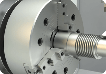
Machining processes (turning, grinding, broaching for keys/splines) determine achievable tolerances and surface finish. Critical bearing journals and sealing surfaces typically require ground finishes with Ra values often below 0.8 µm depending on bearing type. Surface treatments — induction hardening, nitriding, carburizing, or chrome plating — increase wear resistance at contact areas while preserving a tough core to resist impact.
Precise concentricity and minimal runout are essential for rotor balance and bearing life. Tolerances should be specified for journal diameter (e.g., Ø30 H7), axial runout (< 0.02 mm typical for medium-speed motors), and radial runout for mating parts. Geometric dimensioning and tolerancing (GD&T) callouts such as cylindricity, coaxiality, and perpendicularity help ensure function under assembly conditions.
Unbalanced shafts cause vibration, bearing overload, and noise. After machining and assembly, perform static and dynamic balancing. Determine first critical speed using rotor inertia and shaft stiffness models — ensure operating speeds avoid resonance or apply damping/shaft stiffening. For rotors close to critical speeds, use ISO balance grades to set permissible residual unbalance.
Shaft failures usually arise from fatigue cracks (near shoulders, keyways), misalignment causing bearing overloading, corrosion pitting, or excessive wear at journals. Early detection via vibration analysis, oil analysis, and visual inspection increases repair options. Depending on damage extent, repairs include welding and regrinding (only with compatible metallurgy and post-heat treatment), sleeving worn journals, or complete shaft replacement when fatigue cracks are present.
Below is a compact table you can adapt into procurement or engineering drawings. It lists typical shaft features and recommended targets for a medium-duty industrial motor.
| Feature | Typical Value / Spec | Notes |
| Material | AISI 1045 / 4140 | Choose 4140 for high fatigue or heat-treated cases |
| Journal Finish | Ra 0.2–0.8 µm | Grinding + polishing recommended |
| Tolerance | Ø H7 / journal | Specify GD&T for coaxiality |
| Runout | < 0.02 mm axial | Measure at seal and coupling faces |
Following these practical guidelines will improve motor reliability, ease maintenance, and reduce unexpected downtime due to shaft-related failures. When in doubt, prioritize inspection (NDT), conservative fits, and proven materials for high-cycle or safety-critical applications.
 +86-13861233850