 2026-06-09
 Content
Precision electrical connector terminals are the individual conductive elements within a connector assembly that make and maintain the electrical contact between mating connectors, wires, or PCB connections. While the connector housing provides physical structure and alignment, the terminal is the component doing the actual electrical work — carrying current, maintaining contact force, and sustaining reliable conductivity across thousands of mating cycles, temperature excursions, vibration events, and years of service life. In high-reliability applications, the terminal's performance is what determines whether the overall connector assembly meets specification or fails in the field.
The word "precision" distinguishes a defined tier of terminal manufacturing from general-purpose alternatives. Precision connector terminals are produced to tighter dimensional tolerances — typically ±0.01mm to ±0.05mm on critical dimensions — using controlled material specifications, validated plating processes, and manufacturing sequences that maintain dimensional consistency across production lots. This level of control is necessary for terminals that must mate reliably with close-tolerance counterparts, operate in automated assembly equipment with defined insertion and extraction forces, or maintain specified contact resistance values over a service life measured in decades rather than years.
The range of applications driving demand for high-precision electrical terminals spans nearly every sector of electronics and electrical engineering — automotive electronics, aerospace avionics, industrial control systems, medical devices, telecommunications infrastructure, and consumer electronics all depend on connector terminals that perform predictably under their specific operating conditions. What constitutes a precision terminal varies somewhat by application: automotive terminals are precision within their context of vibration resistance and temperature cycling; aerospace terminals are precision within a tighter context of weight, altitude, and EMI performance; medical terminals operate within requirements for biocompatibility and sterilization resistance. Understanding which precision tier your application requires is the starting point for effective sourcing.
Connector terminals are categorized by their connection method — both at the wire or PCB interface and at the mating interface. The geometry and manufacturing method differ significantly across these categories, and selecting the correct type is a prerequisite to any further specification work.
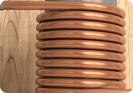
Precision crimp terminals are the dominant type in wire-to-connector applications across automotive, aerospace, and industrial markets. The terminal is manufactured with a crimp barrel — a cylindrical or open-barrel section that is deformed around a stripped wire conductor using a calibrated crimp tool, creating a gas-tight mechanical and electrical connection. In a properly executed precision crimp, the crimp deformation displaces oxides from both the wire strands and the terminal barrel interior, creating metal-to-metal contact that is more reliable and lower-resistance than a solder joint in vibration-prone environments. Precision crimp terminals are manufactured to match specific wire gauges and strand counts — using a terminal designed for 20 AWG on an 18 AWG wire, or using incorrect crimp tooling, results in a connection that fails dimensional and pull-force specifications regardless of how it looks visually.
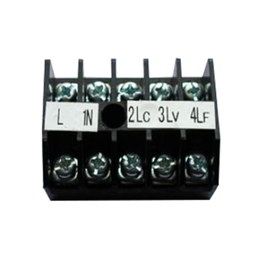
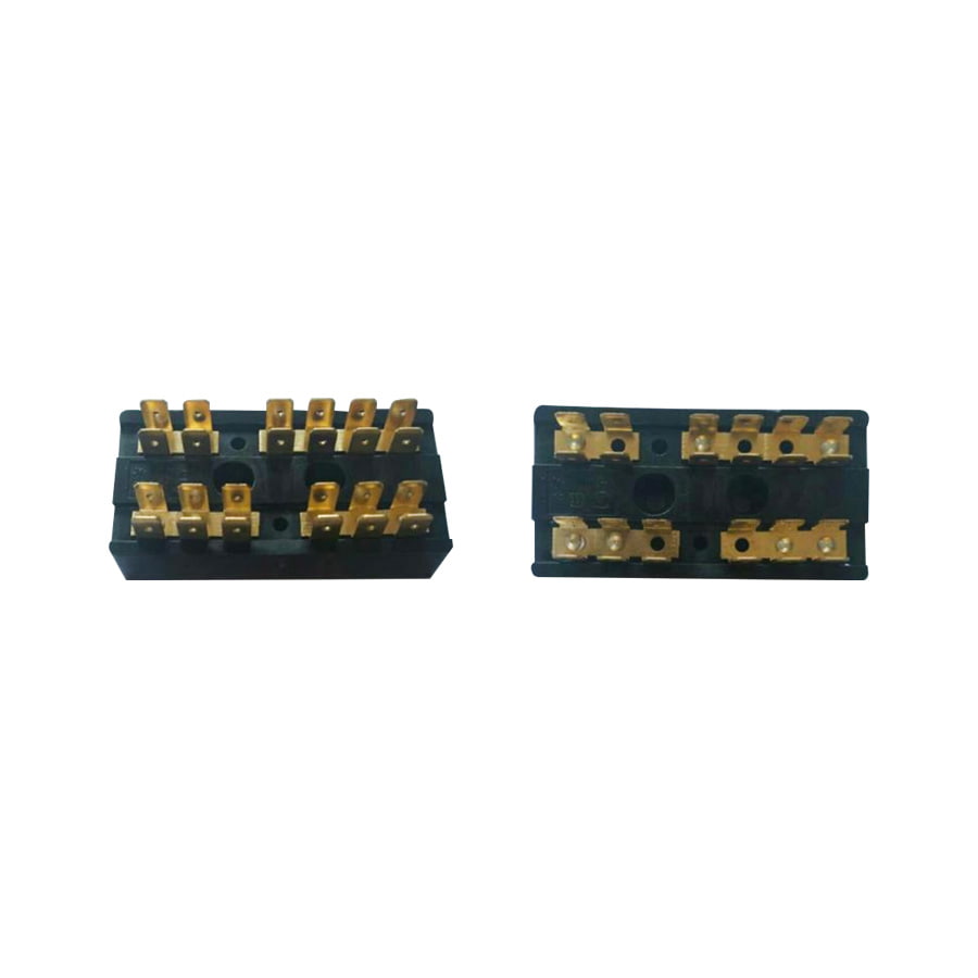
Precision PCB connector terminals are the contact elements in board-mount connectors — headers, receptacles, edge connectors, and mezzanine connectors that interface between a printed circuit board and a mating wire harness, cable assembly, or adjacent board. These terminals are typically stamped and formed from copper alloy strip, then pressed into a housing or soldered or press-fit directly into PCB through-holes or surface mount pads. Dimensional precision is critical because the terminal must register accurately with the connector housing retention features, align with mating contacts within a defined positional tolerance, and generate the correct normal contact force during mating without exceeding the connector's rated insertion force. In high-density connectors with 0.5mm or 0.4mm pitch, the manufacturing tolerance on the terminal profile directly determines whether the connector can be reliably assembled at all.
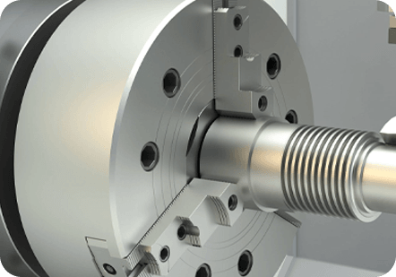
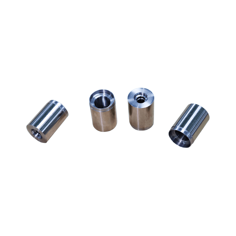
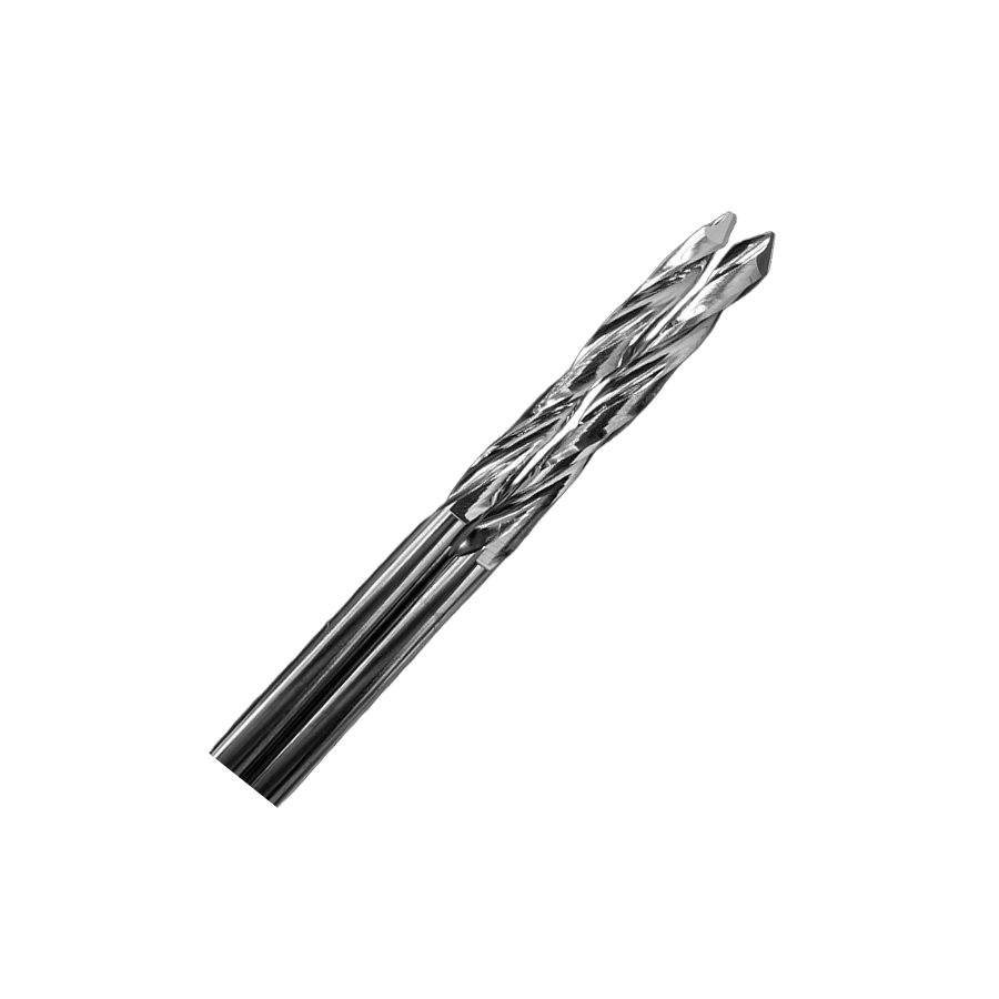
Machined pin and socket terminals — produced by screw-machining or CNC turning from solid copper alloy rod rather than by stamping — represent the highest precision tier in electrical connector terminals. The turned manufacturing process produces terminals with very tight dimensional tolerances, excellent surface finish, and highly consistent geometry that stamped terminals cannot match at fine pitches or complex cross-sections. They are used in mil-spec circular connectors (MIL-DTL-38999, MIL-DTL-26482), aerospace rectangular connectors, high-reliability instrumentation connectors, and medical implant applications. The trade-off versus stamped terminals is cost — machined terminals are significantly more expensive per unit — and the limitation that complex spring-contact geometries achievable by stamping are difficult or impossible to replicate in a machined form.
Spring-loaded contact terminals — including pogo pins (spring-probe contacts) and leaf spring contacts — use an integrated spring element to maintain contact force across variations in mating distance and alignment. Precision pogo pin terminals consist of a plunger, barrel, and internal spring, machined to tight tolerances and plated for contact performance. They are used in test fixtures, battery contacts, board-to-board connections in compact consumer electronics, and any application where a small amount of axial float in the mating interface must be accommodated without losing contact. Spring contact terminals require material and manufacturing precision across multiple components simultaneously — plunger diameter and surface finish, barrel bore tolerance, spring rate and free length — and any dimensional deviation accumulates through the assembly to affect both contact force and electrical performance.
The base metal of a precision electrical terminal determines its electrical conductivity, spring properties, strength, machinability or stampability, and resistance to stress relaxation over time and temperature. Most precision connector terminals use copper alloys — the specific alloy is a deliberate engineering choice, not an arbitrary one.
| Material | Conductivity (% IACS) | Strength | Typical Application |
| Copper (C11000) | 100% | Low | High-current bus bars, lugs |
| Copper-Beryllium (C17200) | 22–28% | Very High | Spring contacts, aerospace sockets |
| Phosphor Bronze (C51000) | 15–20% | High | Stamped spring contacts, PCB terminals |
| Brass (C26000) | 28% | Medium | Machined pins, general-purpose terminals |
| Copper-Nickel-Silicon (C70250) | 40–45% | High | Automotive, high-temp connectors |
| Stainless Steel | 2–3% | Very High | Structural contacts, medical applications |
Copper-beryllium deserves particular attention for high-reliability spring contact applications. Its combination of very high strength, excellent spring properties, and adequate conductivity makes it the material of choice for precision socket contacts in mil-spec and aerospace connectors where contact force must be maintained over thousands of mating cycles and extreme temperature ranges. The health and safety requirements associated with beryllium machining add cost and handling requirements that must be factored into sourcing decisions, but for applications where the spring performance is critical, no other commercially available material fully replicates its combination of properties. Copper-nickel-silicon alloys provide a beryllium-free alternative with good but not equivalent spring performance, and are used in many automotive applications where the temperature and cycle requirements are somewhat less demanding.
The plating on a precision electrical connector terminal does more than protect the base metal from corrosion. It is the actual contact surface — the material whose hardness, oxide behavior, and friction coefficient determine contact resistance, fretting wear resistance, insertion force, and the terminal's ability to maintain low contact resistance over its rated service life. Plating selection is an engineering decision with performance consequences, not just a surface treatment choice.
Gold plating is the premier choice for high-reliability precision connector terminals in aerospace, medical, military, and high-frequency signal applications. Gold does not form an oxide layer under any normal operating conditions, which means contact resistance stays low and predictable over the terminal's full service life without the need for contact wipe to break through oxide films. Hard gold (gold alloyed with small amounts of cobalt or nickel) is used on mating contact surfaces for its superior wear resistance compared to pure soft gold — typically specified at 0.75–1.25 microns over a nickel underplate of 1.25–2.5 microns. The nickel underplate is important: it acts as a diffusion barrier preventing base metal atoms from migrating into the gold layer over time, which would degrade contact performance. Gold plating carries a cost premium that is significant in high-pin-count connectors but is justified by the performance consistency it provides in demanding applications.
Matte tin plating is the standard finish for high-volume precision crimp terminals in automotive and industrial applications. Tin forms a thin, soft oxide layer that is easily displaced during contact mating — the contact wipe action that occurs as the terminal slides into its mating socket breaks through the oxide and establishes metal-to-metal contact. The result is reliably low contact resistance at a fraction of the cost of gold plating. The limitation is fretting corrosion — in vibration-prone environments, micro-movement at the contact interface causes the tin oxide to accumulate at the contact point, progressively increasing contact resistance. For automotive connectors, minimum tin plating thickness is typically 1.0–1.5 microns over a copper or copper-alloy underplate; below this, porosity in the tin layer accelerates base metal corrosion. Tin-lead plating, while offering better performance than pure tin in some respects, is restricted by RoHS regulations in consumer and most commercial applications, limiting its use to specific exempted applications.
Silver plating provides the highest electrical conductivity of any common contact plating material and is used in high-current terminals, RF connector contacts, and applications where thermal conductivity at the contact interface is important. Silver tarnishes in environments containing sulfur compounds, forming silver sulfide on the surface — this tarnish layer is slightly resistive but is generally disrupted by contact wipe during mating and does not cause contact failure under normal connection and reconnection use. In applications where connectors are mated once and remain static (such as some industrial power connectors), silver tarnish can accumulate over time without being wiped away, potentially increasing contact resistance. Silver plating thickness for precision connector terminals is typically 3–8 microns; thinner deposits may not provide complete coverage over surface irregularities in the base metal.
Evaluating and comparing precision electrical connector terminals requires reference to specific performance parameters that reflect real operating conditions. The following specifications appear in datasheets and test reports and represent the performance criteria that distinguish precision terminals from general-purpose alternatives.
Precision connector terminal performance claims should be supported by compliance with recognized industry standards. The standards landscape varies by application sector, but the following represent the key frameworks relevant to most precision electrical terminal sourcing decisions.
| Standard | Scope | Primary Market |
| IEC 60352 | Solderless connections including crimp terminals | Global industrial / commercial |
| MIL-DTL-39029 | Mil-spec crimp contacts for circular connectors | US defense / aerospace |
| USCAR-21 | Automotive connector terminal performance requirements | Automotive OEM supply chain |
| IPC/WHMA-A-620 | Wire harness assembly requirements including crimp quality | Electronics manufacturing |
| EIA-364 | Electrical connector and socket test procedures | US electronics industry |
| RoHS / REACH | Restriction of hazardous substances in materials | EU and global export markets |
| IATF 16949 | Quality management system for automotive supply chain | Automotive OEM supply chain |
For aerospace and defense applications, MIL-spec qualification is not optional — it is a contractual and regulatory requirement. MIL-DTL-39029 qualified crimp contacts, for example, must be sourced from manufacturers listed on the Qualified Products List (QPL) maintained by the Defense Logistics Agency. Using non-QPL contacts in mil-spec connector assemblies is a non-compliance regardless of the terminal's actual dimensional and performance characteristics. For automotive applications, IATF 16949 certification of the terminal manufacturer indicates a quality management system structured for automotive production volumes and change control requirements, and is increasingly a minimum supplier qualification requirement for tier-1 automotive supply chain participants.
Datasheet specifications represent the terminal's design intent and type-test results. What happens in production — lot-to-lot dimensional consistency, plating thickness distribution, material traceability — determines whether purchased terminals actually perform to specification across thousands or millions of parts. These are the sourcing evaluation factors that go beyond the published specification.
Precision crimp and PCB connector terminals are manufactured at high speed on progressive stamping dies or screw machines — processes where tooling wear causes gradual dimensional drift between die maintenance intervals. Suppliers who practice statistical process control (SPC) on critical dimensions — monitoring Cpk values in real time and triggering tooling adjustments before dimensions approach specification limits — produce significantly more consistent output than those who rely on periodic incoming inspection. When evaluating precision terminal suppliers, ask for actual SPC data from recent production lots, not just a statement that SPC is used. Cpk values above 1.33 on critical dimensions indicate a process that is both centered and sufficiently capable to produce very low rates of out-of-specification parts.
Plating thickness and composition must be controlled within tight limits to ensure performance consistency. Gold plating that varies from 0.5 microns in some areas to 2.0 microns in others on the same terminal lot indicates poor process control — parts with thin plating may fail porosity requirements while parts with excess plating drive unnecessary precious metal cost. Reputable precision terminal manufacturers use X-ray fluorescence (XRF) measurement of plating thickness as a routine process control tool, with measurements taken at defined points on the terminal and documented as part of the production record. Request plating thickness measurement data — not just a certificate stating conformance — when qualifying a new supplier.
For precision electrical terminals used in aerospace, medical, and defense applications, full material traceability from raw material mill certificate to finished part is a standard requirement. The base metal alloy specification, temper, lot number, and mechanical property test results must be documented and retained. Plating chemistry, tank analysis records, and anode material certifications are part of the traceability package. If a field failure occurs, this documentation enables root cause analysis to determine whether a material substitution or process variation contributed to the failure. Suppliers who cannot provide complete material traceability on request are not appropriate for regulated or high-reliability applications, regardless of their price competitiveness.
For qualified precision connector terminals in automotive or aerospace supply chains, any change to materials, manufacturing process, tooling, or facility that could affect terminal dimensions or performance requires formal notification to customers before implementation — and in some cases requires re-qualification testing. This change notification process, sometimes called "process change notification" (PCN) or "change impact analysis" in automotive quality systems, ensures that form-fit-function changes don't reach production without the customer's knowledge. When qualifying precision terminal suppliers, verify that their quality system includes a documented PCN process and that they have a track record of providing advance notice of changes rather than disclosing them after the fact during a customer audit.
 +86-13861233850