 2026-06-12
 Content
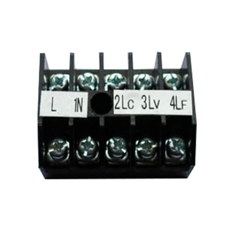
A power terminal board is an electrical component used to connect, distribute, and manage wiring in a structured and organized way. Think of it as a central hub where multiple wires meet — it lets you safely route electrical power or signals from one source to multiple destinations without messy, unreliable wire splicing. You'll find power terminal boards inside control panels, industrial machinery, HVAC systems, home automation setups, and even consumer electronics.
At its core, a terminal board consists of a series of individual terminal blocks mounted on an insulating base. Each terminal block has metal conductive parts (usually copper or brass) that grip the wire and maintain a secure electrical connection. The insulating housing — typically made from nylon, polyamide, or polycarbonate — keeps those connections safe and separated from each other.
Unlike simple wire nuts or butt connectors, a power terminal board is a permanent, serviceable solution. You can add or remove wires without disturbing other connections, label each terminal for easy identification, and test voltage or continuity at individual points. That's why electricians and engineers rely on them so heavily for professional installations.
Not all power terminal boards are the same. The right type depends on your voltage and current requirements, the environment where it'll be installed, and how the wires need to be connected. Here's a breakdown of the most widely used types:
DIN rail terminal boards are the most common type used in industrial and commercial electrical panels. They snap directly onto a standardized DIN rail (a metal mounting strip), making installation and replacement fast and tool-free in most cases. They're modular — you can add or remove individual terminal blocks as your wiring needs grow or change. DIN rail boards are available in a wide range of current ratings, from 10A for control wiring up to 125A or more for heavy power distribution.
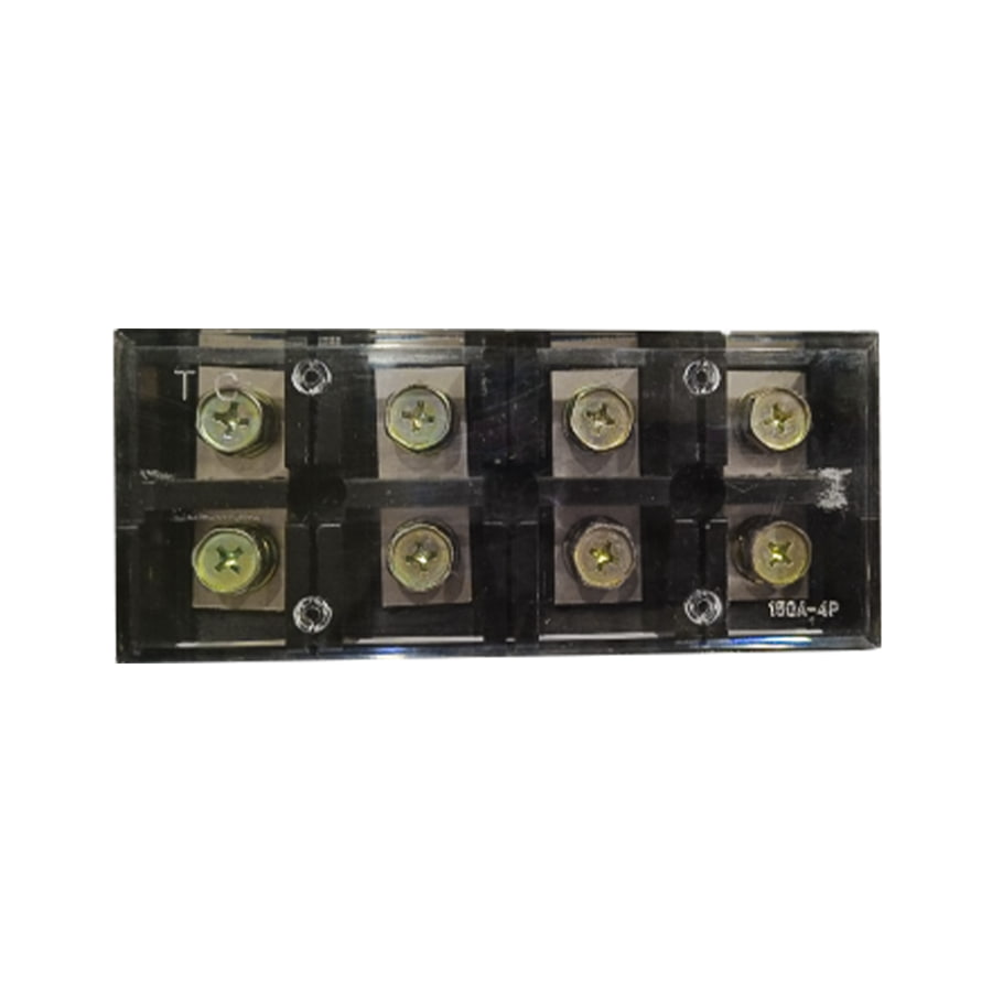
Screw-type terminal boards use a threaded screw to clamp down on the wire. They're extremely common, low-cost, and reliable. The wire is inserted into the terminal opening and the screw is tightened to lock it in place. These are great for solid wire connections, but for stranded wire, it's a good practice to use ferrules — small metal sleeves crimped onto the wire end — to prevent individual strands from breaking or loosening over time.
Spring-clamp (or push-in) terminal boards use a spring mechanism to hold the wire. You press a lever or tool to open the clamp, insert the wire, and release — the spring snaps shut and grips the wire firmly. These are faster to wire than screw types, and they handle vibration better, which makes them popular in automotive, transportation, and vibration-heavy industrial environments.
Barrier terminal boards — often called terminal strips — have physical barriers (ribs) between each connection point. They're mounted directly to a surface using screws and are common in older electrical equipment, marine wiring, and hobby electronics. They're simple, rugged, and inexpensive. However, they're less modular than DIN rail types and typically rated for lower current applications.
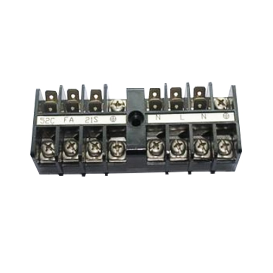
Power distribution terminal blocks are a specialized type designed specifically to take one high-current input and distribute it across multiple output terminals. Instead of a one-in, one-out design, they feature a common bus bar on one side connected to multiple smaller output terminals. These are frequently used in panel boards, motor control centers, and anywhere you need to branch power to several circuits from a single feed.
When shopping for or specifying a power terminal board, the spec sheet can look overwhelming. Here are the most important parameters to focus on:
| Specification | What It Means | Typical Range |
| Voltage Rating | Maximum voltage the terminal can safely handle | 300V – 1000V |
| Current Rating | Maximum continuous current capacity | 10A – 300A+ |
| Wire Gauge (AWG or mm²) | Wire size range the terminal accepts | 28 AWG – 2/0 AWG |
| Pole Count | Number of individual connection points | 2 – 24+ poles |
| IP Rating | Protection level against dust and moisture | IP20 – IP67 |
| Temperature Range | Operating temperature limits | -40°C to +120°C |
| Material (Housing) | Insulation material affecting heat and flame resistance | Nylon, PA66, PC |
Always spec your terminal board with a safety margin. If your circuit runs at 20A, don't choose a terminal rated for exactly 20A — go for one rated at 30A or higher. The same logic applies to voltage. Oversizing slightly reduces heat buildup at the connection and dramatically improves long-term reliability.
Power terminal boards appear in a surprisingly wide range of applications, from heavy industrial machinery to small DIY electronics projects. Here are some of the most common places you'll find them:
Proper wiring technique makes a huge difference in safety and longevity. A loose or improperly prepared connection can arc, overheat, and eventually cause a fire. Follow these best practices every time:
Strip only as much insulation as the terminal requires — typically 6mm to 10mm. Stripping too little means the conductor won't make full contact; stripping too much leaves bare wire exposed outside the terminal, creating a shock or short-circuit hazard. Use a quality wire stripper calibrated to the wire gauge you're working with.
If you're using stranded wire with screw-type terminals, always crimp a ferrule onto the stripped end. Without ferrules, individual strands can splay out, get trapped under the screw, or break over time due to repeated screw torque. Ferrules give stranded wire a solid, clean end that behaves like solid wire in the terminal clamp.
Over-tightening screw terminals can damage the wire insulation or deform the conductor. Under-tightening leads to resistance buildup and eventual arcing. Most quality terminal boards specify a torque value (e.g., 0.5 Nm for small terminals, up to 4 Nm for large power terminals). Use a calibrated torque screwdriver whenever possible, especially in critical applications.
A power terminal board with no labels is a troubleshooting nightmare. Use terminal markers — small plastic or clip-on labels — to number or name each connection point. Good labeling lets you trace wires quickly, reduces the chance of wiring errors during installation, and speeds up maintenance work months or years down the road.
Always follow your regional or industry color-coding standard. In the US (NEC), black and red are typically used for hot conductors, white for neutral, and green or bare for ground. In European (IEC) wiring, brown is live, blue is neutral, and green/yellow is protective earth. Using the correct colors makes the installation instantly readable to any qualified electrician who works on it later.
Choosing the right terminal board comes down to a clear set of criteria. Work through these questions before making a purchase:
A power terminal board that's properly installed still needs periodic attention to stay safe and functional. Here's what to keep in mind:
Metal conductors and housing materials expand and contract with temperature cycles over time. This thermal cycling can gradually loosen screw connections. In high-current or high-vibration environments, inspect and retorque all terminal screws at least once a year, or on whatever maintenance schedule your application requires.
Yellowing, browning, or blackening of the terminal housing is a red flag. It usually indicates that the terminal has been running too hot — often due to a loose connection, an overloaded circuit, or an undersized terminal. Replace any discolored terminals immediately and find the root cause before re-energizing the circuit.
Dust, condensation, and contaminants on terminal boards can cause tracking — a surface creep of electricity across the insulating material — which leads to short circuits and equipment damage. Keep enclosures sealed, use anti-condensation heaters in humid environments, and blow out accumulated dust with compressed air during scheduled maintenance.
Whenever you add, change, or remove a connection on a terminal board, update your wiring diagram immediately. Out-of-date documentation is one of the most common causes of wiring errors during repairs or modifications. Keep a current diagram either on the inside of the panel door or in a digital maintenance system accessible to your team.
 +86-13861233850