 2026-05-08
 Content
Drive shaft manufacturing is the process of designing, forming, machining, assembling, and testing the rotating mechanical components that transmit torque and rotational power from an engine or motor to wheels, axles, or other driven components. A drive shaft — also called a propeller shaft, prop shaft, or driveshaft depending on the application — must simultaneously handle high torsional loads, resist bending under dynamic forces, operate at precise balance tolerances, and survive years of cyclic fatigue loading without failure. Getting the manufacturing process right is therefore not just a matter of cutting metal to shape; it requires a tightly controlled sequence of material selection, forming operations, precision machining, heat treatment, surface finishing, assembly, and rigorous quality inspection.
Drive shafts are used across an enormous range of applications — passenger cars, commercial trucks, agricultural machinery, industrial gearboxes, marine propulsion systems, aerospace actuation systems, and wind turbines all rely on manufactured drive shafts of varying sizes, materials, and performance requirements. While the specific processes vary by application, the fundamental manufacturing challenges are consistent: achieving the required dimensional accuracy, mechanical strength, torsional stiffness, and rotational balance within cost and production rate targets.
This article walks through the complete drive shaft production process — from raw material selection through final inspection — covering both automotive driveshaft manufacturing and industrial shaft production, with practical detail on the equipment, processes, tolerances, and quality controls involved at each stage.
The material chosen for a drive shaft determines its strength, weight, fatigue life, machinability, and cost. Drive shaft manufacturers select from several material categories depending on the torque requirements, operating speed, weight targets, and production volume of the application.
Carbon and alloy steels remain the dominant material for drive shaft manufacturing across automotive, truck, and industrial applications. Medium carbon steels such as SAE 1045 are widely used for solid shafts in lower-torque applications due to their good combination of strength, toughness, and machinability at relatively low cost. For higher-torque or fatigue-critical applications, alloy steels such as SAE 4140 (chromium-molybdenum steel) and SAE 4340 (nickel-chromium-molybdenum steel) are specified. These grades develop significantly higher yield and tensile strength after heat treatment — 4140 typically achieves 650–1,000 MPa yield strength depending on heat treatment, while 4340 can reach 1,400 MPa or higher in demanding aerospace and racing applications. Case-hardening steels such as SAE 8620 are used when a hard, wear-resistant surface combined with a tough core is needed, as in splined drive shafts that must resist fretting and wear at the spline interface.
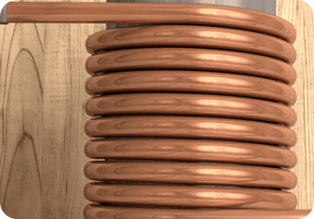
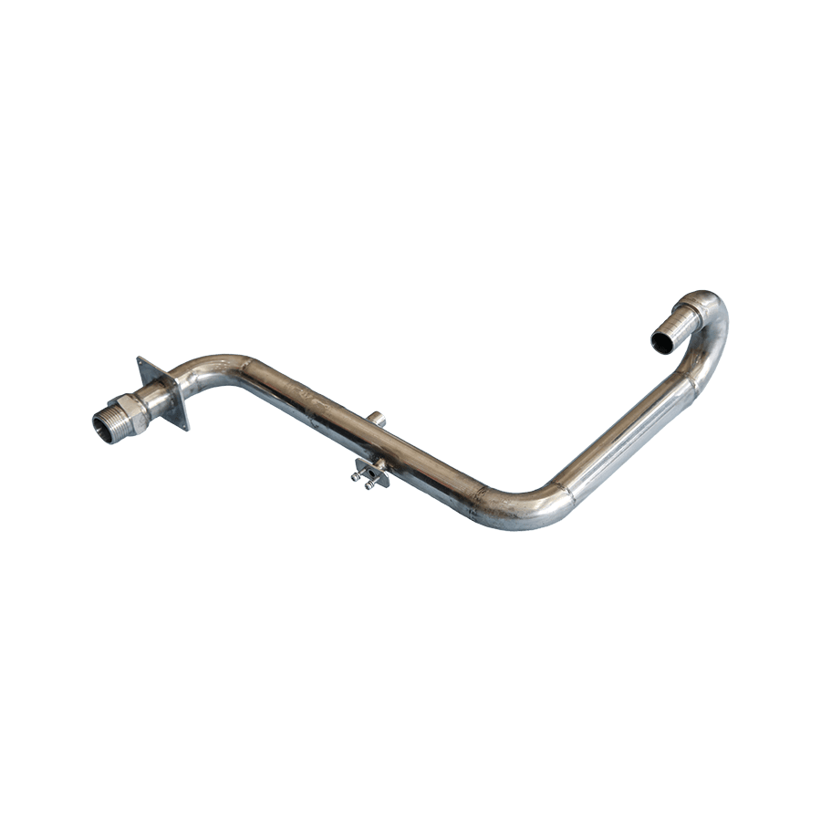
Most automotive and truck driveshafts use hollow steel tubes rather than solid bars. A hollow tube provides nearly the same torsional stiffness and strength as a solid shaft of the same outer diameter but at a fraction of the weight, because torsional stress is highest at the outer surface and the central material contributes little to torsional resistance. Seamless cold-drawn steel tubes (typically 1026 or 1020 DOM — drawn over mandrel) are the standard for automotive driveshaft tube manufacturing. The tube wall thickness, outer diameter, and steel grade are selected through torsional and bending stress calculations to meet the vehicle's torque and critical speed requirements.
Aluminum driveshafts — primarily manufactured from 6061-T6 or 7075-T6 alloy tube — offer a 60–65% weight reduction compared to equivalent steel shafts. This weight saving improves vehicle fuel economy, reduces rotating inertia (improving acceleration response), and lowers NVH (noise, vibration, harshness) by raising the shaft's critical speed. Aluminum driveshaft manufacturing is common in performance vehicles, light trucks, and racing applications. The main manufacturing challenge with aluminum is achieving reliable yoke or end fitting attachment — aluminum's lower strength requires careful joint design, often using friction welding or press-fit-and-bolt attachment methods rather than conventional arc welding.
Carbon fiber reinforced polymer (CFRP) driveshafts offer the highest specific stiffness and lowest weight of any drive shaft material, making them the preferred choice in high-performance automotive, motorsport, and aerospace applications where weight and rotational dynamics are paramount. CFRP driveshaft manufacturing uses filament winding — a process where carbon fiber tows impregnated with epoxy resin are wound over a mandrel at precise angles to develop the required torsional and bending stiffness — followed by curing in an autoclave or oven. Metal end fittings are bonded and mechanically fastened to the composite tube. Carbon fiber shafts can achieve critical speeds 2–3 times higher than equivalent steel shafts, allowing single-piece driveshafts to replace two-piece steel assemblies in longer applications.
A complete driveshaft manufacturing process involves multiple sequential operations. Each step builds on the previous one, and quality control at intermediate stages is essential to avoid compounding errors that affect final product performance.
Raw material arrives at the drive shaft manufacturer as cut-to-length bar stock, seamless tube, or coiled tube depending on the production method. Cold saw cutting or abrasive cutoff wheels cut the material to rough length with a small machining allowance. Cut ends are deburred to remove sharp edges that could damage downstream tooling or create stress concentrations. For hollow tube shafts, the tube straightness is verified at this stage — tubes with excessive bow are rejected or straightened before further processing, because tube straightness directly affects final shaft runout and balance.
The end fittings of a driveshaft — yokes, flanges, and stub shafts — are typically manufactured separately by hot forging or cold forging before being attached to the tube. Hot forging heats the steel billet to 1,100–1,250°C and shapes it under high press forces in a die set. Hot forging produces parts with excellent grain flow aligned to the part geometry, resulting in higher fatigue strength than machined-from-bar alternatives. The forged blanks are then trimmed, shot blasted to remove scale, and passed to machining operations. For high-volume automotive production, cold forging of smaller end fittings is also common — cold forging produces tighter dimensional tolerances and better surface finish directly from the forge, reducing subsequent machining requirements.
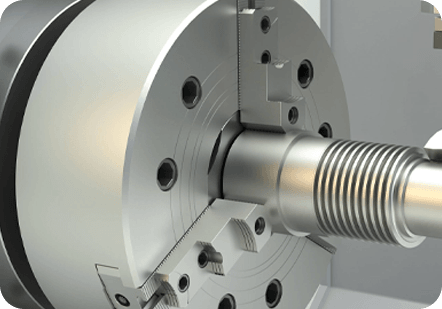
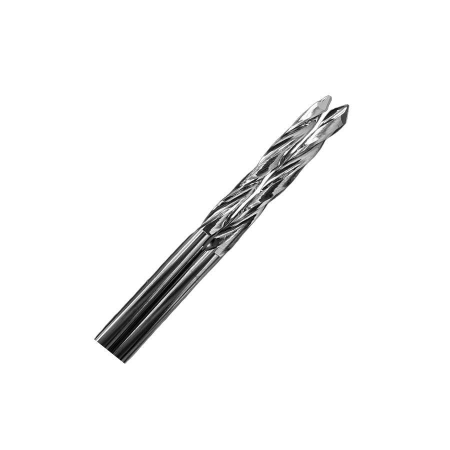
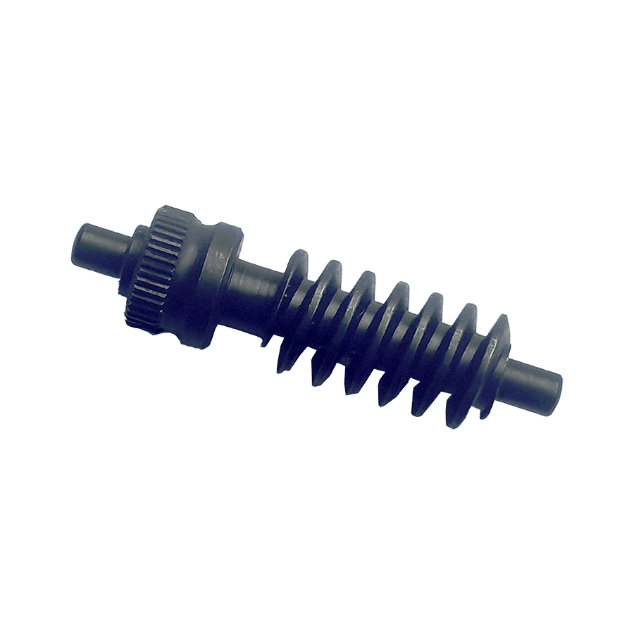
Precision turning operations establish the critical diameters, bearing journal surfaces, and shoulder features of the drive shaft. CNC turning centers machine the shaft between centers (using center holes ground into both ends) to maintain concentricity across all turned diameters. Bearing journal tolerances are typically h6 or k6 fits — requiring diametral accuracy within 10–20 micrometers — achieved through finish turning followed by cylindrical grinding. Splined sections are produced by hobbing, broaching, or CNC milling depending on the spline geometry and volume. External splines on automotive driveshafts are most commonly cold-rolled rather than cut — cold rolling displaces metal outward to form the spline teeth, producing a work-hardened surface with compressive residual stresses that significantly improve fatigue life compared to machined splines.
For steel driveshafts, the tube and end yokes or flanges are joined by welding — most commonly friction welding (rotary or linear) or MIG/MAG welding. Friction welding is the preferred method in high-volume automotive driveshaft production because it produces consistently high-quality, fully consolidated welds without filler metal, porosity, or the heat-affected zone (HAZ) issues associated with fusion welding. In the friction welding process, one component rotates at high speed while the other is held stationary and pressed against it axially; frictional heat plasticizes the interface material, and when the rotation stops, an axial forge force consolidates the joint. Friction-welded driveshaft joints achieve 90–100% of the parent metal strength and can be produced at cycle times of 15–30 seconds per joint. For lower-volume industrial and commercial vehicle shafts, MIG welding with appropriate preheat and post-weld inspection is the standard joining method.
Heat treatment after machining and welding develops the required mechanical properties in the shaft material. Through-hardening (quench and temper) of alloy steel shafts brings the material to the specified hardness and tensile strength — typically 28–35 HRC for general industrial shafts and 38–48 HRC for high-performance applications. Induction hardening is widely used to selectively harden bearing journals, splines, and other wear surfaces on the shaft without hardening the entire component. The induction process heats a localized zone very rapidly using electromagnetic induction, followed by immediate quench cooling, producing a hard martensitic surface layer (typically 1–3 mm deep) with a tough unhardened core. Induction-hardened surfaces typically reach 55–62 HRC and have beneficial compressive residual stresses that enhance fatigue resistance. After hardening, low-temperature tempering at 150–200°C relieves quench stresses without significantly reducing hardness.
Heat treatment and welding invariably introduce some distortion into the shaft. Straightening is performed on a press straightening machine or a CNC-controlled straightening system that measures the shaft runout at multiple points and applies controlled bending forces to bring the shaft within the specified straightness tolerance — typically 0.2–0.5 mm total indicator runout (TIR) over the full shaft length for automotive applications, and as tight as 0.05 mm TIR for precision industrial shafts. Straightening must be done carefully to avoid overstressing the shaft or introducing residual stresses that cause re-bending in service.
Cylindrical grinding of bearing journals and sealing surfaces brings dimensions to final tolerance and achieves the required surface finish. Bearing journals on precision industrial shafts are typically ground to Ra 0.4–0.8 µm and held to roundness within 5 micrometers. Centerless grinding is used for through-hardened pins and smaller shaft diameters where between-centers grinding is impractical. Some applications require superfinishing (honing or lapping of bearing journals to Ra below 0.1 µm) to minimize bearing friction and wear. Surface shot peening is applied in fatigue-critical areas — particularly at fillet radii, spline runouts, and weld toes — to introduce beneficial compressive residual stresses that extend fatigue life by 20–50% compared to non-peened surfaces.
Dynamic balancing is one of the most important operations in driveshaft manufacturing and one of the most frequently misunderstood. Any rotating shaft has mass distributed around its rotational axis, and if that mass distribution is not perfectly symmetric, the shaft generates centrifugal forces as it rotates that produce vibration, noise, bearing loads, and ultimately fatigue damage in the drivetrain. The higher the operating speed, the more critical balance becomes — even small imbalance masses create large centrifugal forces at high RPM.
Driveshafts are balanced on dynamic balancing machines that spin the shaft and measure the vibration forces generated in two correction planes simultaneously. The machine calculates the magnitude and angular position of the imbalance in each plane and displays the correction required. Correction is made by adding balance weights (typically small clamps or welded slugs), drilling or milling material from heavy spots, or adding correction clay for initial setup trials. Automotive driveshafts are typically balanced to ISO 1940 Grade G6.3 or better, meaning the residual specific unbalance is less than 6.3 gram-millimeters per kilogram of shaft mass per correction plane. High-speed or precision shafts are balanced to G2.5 or G1.0. After balancing, the shaft is re-spun to verify that residual imbalance is within specification before it passes to final inspection.
Drive shaft manufacturers apply a layered quality inspection strategy that combines in-process checks at each manufacturing stage with final inspection of the completed assembly. The table below summarizes the key inspection methods used in drive shaft manufacturing and what each one verifies:
| Inspection Method | What It Checks | Stage Applied |
| CMM Dimensional Inspection | All critical diameters, lengths, GD&T features | Post-machining, final |
| Runout Measurement (TIR) | Shaft straightness and concentricity | Post-straightening, final |
| Hardness Testing (Rockwell) | Surface and core hardness after heat treatment | Post-heat treatment |
| Magnetic Particle Inspection (MPI) | Surface and near-surface cracks, weld defects | Post-weld, post-grind, final |
| Ultrasonic Testing (UT) | Internal defects, weld integrity, material flaws | Post-weld, critical applications |
| Dynamic Balance Test | Residual imbalance in two correction planes | Post-assembly, final |
| Torsional Fatigue Testing | Shaft life under cyclic torque loading | Development, periodic production audit |
| Surface Roughness Measurement | Ra and Rz of bearing journals and seal surfaces | Post-grinding, final |
| Spline Profile Inspection | Spline tooth profile, lead, pitch, and fit class | Post-spline operation, final |
While the core manufacturing processes are similar across applications, drive shaft production varies significantly in detail depending on the industry and the specific performance requirements involved.
Passenger car and light truck driveshaft manufacturing is characterized by high volume, tight cost control, and rigorous OEM quality standards. Production lines for automotive propshafts typically use automated friction welding of forged yokes to DOM steel tubes, CNC balancing machines integrated into the line, and 100% end-of-line testing including dimensional verification, weld integrity checks, and dynamic balance confirmation. Constant velocity (CV) joint assemblies for front-wheel drive axle shafts involve precision grinding of ball tracks, controlled heat treatment of the inner and outer races, and clean-room assembly to prevent contamination of the grease-filled joint. Automotive driveshaft manufacturers must comply with IATF 16949 quality management standards and submit PPAPs (Production Part Approval Processes) to OEM customers before production launch.
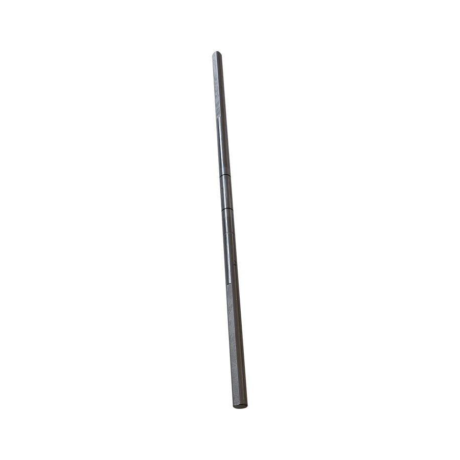
Industrial drive shaft production for gearboxes, pumps, compressors, and heavy machinery typically involves lower volumes, larger shaft sizes, and heavier section thicknesses than automotive work. Shafts are often machined from solid bar stock rather than tube, and the machining operations involve heavy roughing cuts followed by semi-finish and finish turning, grinding, and keyway broaching or milling. Larger industrial shafts are normalized or annealed before machining to relieve forging or rolling stresses, then quench-and-tempered to final properties. Non-destructive testing coverage is typically more extensive on industrial shafts — 100% ultrasonic inspection of raw material and magnetic particle inspection of finished surfaces is common for critical applications such as gearbox output shafts in wind turbines or marine propulsion systems.
Aerospace driveshaft manufacturing — for helicopter tail rotors, aircraft accessory drives, and actuation systems — demands the highest precision, material traceability, and process documentation of any drive shaft application. Materials are typically aerospace-grade 4340M (VAR — vacuum arc remelted) steel, titanium alloy (Ti-6Al-4V), or CFRP. Every material lot is traceable to its melt certification and mechanical test records. All machining, heat treatment, and surface treatment operations are performed to controlled, qualified processes with full records retained for the life of the aircraft. NDT inspection includes fluorescent penetrant inspection (FPI) of all surfaces, ultrasonic inspection of forgings, and dimensional verification on CMMs with calibration traceable to national standards. Finished aerospace shafts undergo proof torque testing before acceptance, and flight-critical shafts may require spin testing at operating speed to verify structural integrity.
Understanding the most frequent failure modes in drive shaft production helps manufacturers implement targeted preventive measures at the right process steps.
A disciplined drive shaft manufacturing process — with clear process controls, in-process measurement, and final verification testing — is what separates driveshafts that quietly deliver hundreds of thousands of kilometers of reliable service from those that generate warranty returns, NVH complaints, and field failures. Investing in process capability at each manufacturing stage is always more cost-effective than discovering defects at final inspection or, worse, in the field.
 +86-13861233850