 2026-03-16
 Content
A precision motor shaft is the mechanical output component of an electric motor — the rotating cylindrical element that transmits torque from the motor's rotor to the driven load through couplings, gears, pulleys, pinions, or direct interference-fit connections. The word "precision" in this context is not a marketing qualifier; it refers to the tight dimensional tolerances, geometric accuracy requirements, and surface finish specifications that distinguish a precision motor shaft from a standard commercial shaft. In applications ranging from medical devices and laboratory instruments to servo drives, robotics, and aerospace actuators, the shaft's dimensional accuracy directly determines system performance — bearing fit quality, coupling concentricity, vibration levels, rotational accuracy, and ultimately the reliability of the entire driven assembly.
Even small deviations from specified shaft geometry can cascade into serious system-level problems. A shaft diameter that is 0.01mm oversize will cause a press-fit bearing to be over-stressed during assembly and may crack the inner race. A shaft with 0.005mm of runout on the bearing journal will impose a cyclical load on the bearing at shaft rotational frequency, dramatically reducing its L10 service life. A shaft with incorrect surface roughness on the bearing seat — too rough — will micro-weld to the bearing inner race during operation, making disassembly destructive. These are not edge cases; they are the routine consequences of sourcing motor shafts to inadequate precision grades, and understanding what makes a precision motor shaft genuinely precise is essential for anyone specifying, procuring, or designing with these components.
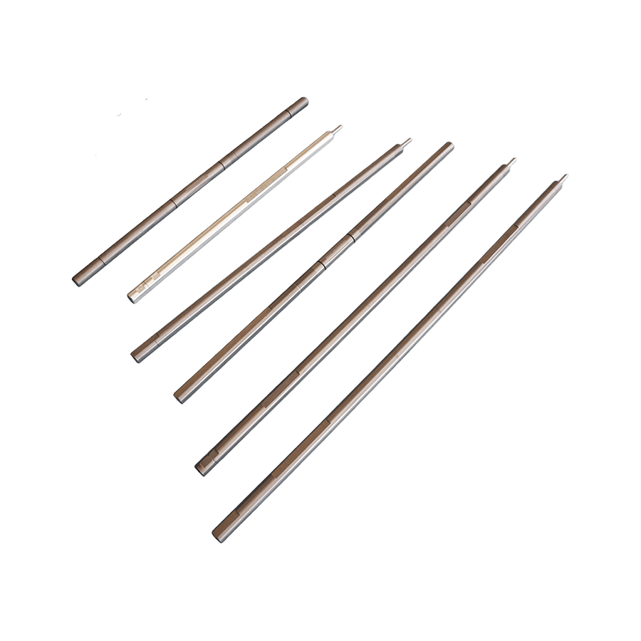
A precision motor shaft is not a simple cylinder — it is a multi-feature machined component in which each zone is designed to interface with a specific mating component, and each interface imposes its own dimensional, geometric, and surface finish requirements. Understanding the function of each feature helps when writing specifications and evaluating supplier capability.
The bearing journals are the cylindrical sections of the shaft that seat inside the motor's rolling element or plain bearings. These are typically the most dimensionally critical sections of the entire shaft. The journal diameter must be held to a tight tolerance — typically IT5 or IT6 grade per ISO 286, which translates to tolerances of ±0.003mm to ±0.008mm on diameters ranging from 5mm to 50mm — to achieve the correct bearing fit. A clearance fit is used for bearings that must be pressed onto the shaft with hand force or light tooling (transition fit), while an interference fit is used where the bearing inner race must be securely locked to the shaft to prevent creep under load. Surface roughness on bearing journals is specified at Ra 0.4 µm to Ra 0.8 µm for rolling element bearings and Ra 0.2 µm or finer for plain hydrodynamic bearings where surface finish directly affects the oil film formation that supports the shaft.
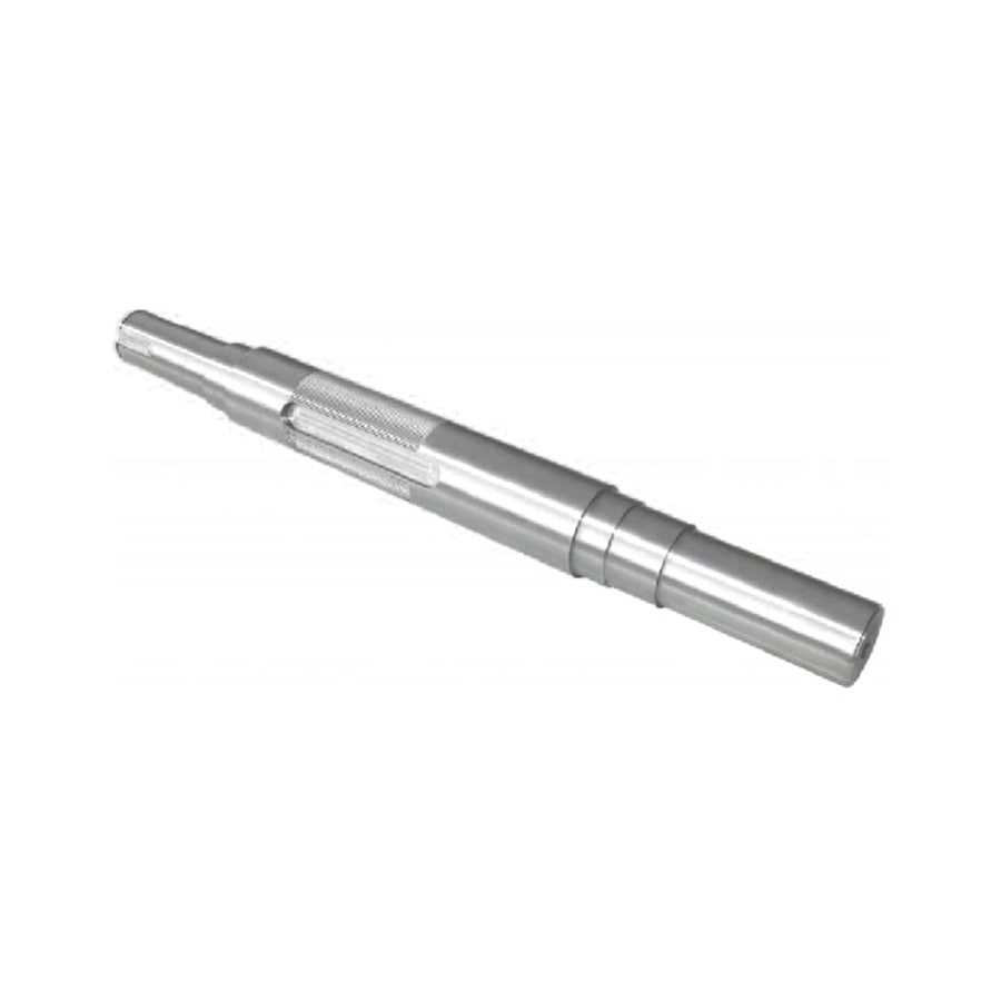
The output or drive end of a precision motor shaft is the section that connects to the load — through a keyed hub, spline coupling, pinion gear, pulley, encoder disc, or other power transmission element. Keyways machined into the shaft provide a positive rotational drive connection that transmits torque without relying on interference alone. Splined shaft ends — both involute and straight-sided profiles — distribute torque across multiple contact points, providing higher torque capacity and better misalignment tolerance than single keyways. Precision ground tapered shaft ends are used in applications requiring easy assembly and disassembly of hubs without a key, where the taper angle creates a self-locking or releasable interference fit depending on the application of an axial clamping nut. Thread features at the shaft end retain coupling hubs, encoder discs, or end caps against axial loads.
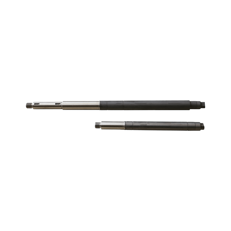
In most electric motor designs, the rotor lamination stack or permanent magnet assembly is interference-fitted directly onto the motor shaft. The rotor mounting zone must have a precisely controlled diameter for a specific interference fit that provides adequate torque transmission without causing the rotor laminations to crack during press-fitting. In high-speed motors, the rotor-to-shaft interference must also resist the centrifugal expansion of the rotor at maximum speed — if the interference is insufficient, the rotor can loosen at speed, causing catastrophic imbalance. The roundness of the rotor mounting zone directly affects the dynamic balance quality achievable after rotor assembly: an out-of-round shaft introduces an eccentricity error into the rotor mass distribution that cannot be fully corrected by subsequent balancing.
Diameter transitions between shaft sections create shoulders that axially locate bearings, rotors, and other components along the shaft. The squareness of these shoulders to the shaft axis — perpendicularity tolerance — determines how squarely bearings and rotors seat, affecting pre-load and axial alignment. Undercut grooves at the base of shoulders and at the ends of ground sections relieve the stress concentration created by abrupt diameter changes, significantly improving the shaft's fatigue life under cyclic torsional and bending loads. On high-cycle precision motor shafts, these undercut radii and their surface finish are as important to service life as the shaft's overall material strength.
Material selection for a precision motor shaft involves balancing machinability and grindability (which determines achievable dimensional precision), mechanical strength and fatigue resistance (which determines load-carrying capability and service life), magnetic properties (critical in applications where the shaft passes through the motor's magnetic circuit), and corrosion resistance (for applications in wet, chemically aggressive, or food-grade environments).
| Material | Typical Grade | Key Properties | Common Application |
| Carbon steel | C45, 1045, S45C | Good strength, machinable, low cost | General industrial motors, HVAC, pumps |
| Alloy steel | 42CrMo4, 4140, SCM440 | High strength, fatigue resistant, heat treatable | Servo motors, high-torque drives, gearbox outputs |
| Case-hardening steel | 16MnCr5, 8620 | Hard surface, tough core, wear resistant | Shafts with integral pinions, high-wear journals |
| Stainless steel | 303, 316, 17-4PH | Corrosion resistant, non-magnetic (austenitic) | Medical devices, food processing, marine motors |
| Titanium alloy | Ti-6Al-4V | High strength-to-weight, non-magnetic, corrosion resistant | Aerospace actuators, MRI-compatible motors |
| Aluminum alloy | 7075-T6, 6061-T6 | Lightweight, non-magnetic, good machinability | Small high-speed motors, UAV drives, robotics |
Many precision motor shaft materials are heat-treated to develop the required mechanical properties — quenching and tempering of alloy steels to achieve tensile strength of 900–1,200 MPa, case carburizing of low-alloy steels to achieve a hard wear-resistant surface with a tough core, or nitriding to achieve an extremely hard surface layer with minimal dimensional distortion. The sequence of heat treatment and precision grinding operations is critical: heat treatment causes dimensional distortion that must be corrected by subsequent grinding. Precision motor shafts are typically rough-machined, heat-treated, straightened if necessary, and then precision-ground to final dimensions. Final grinding after heat treatment — not before — is the only reliable way to achieve both the required mechanical properties and the tight dimensional tolerances of a precision motor shaft simultaneously.
Tolerance specification is the technical heart of precision motor shaft design. Too loose and the shaft cannot perform its intended function; unnecessarily tight and the manufacturing cost escalates without benefit. Understanding which tolerances matter most for each feature, and what values are appropriate for different applications and speeds, is what separates a well-specified precision motor shaft drawing from one that is either under-specified or impractically tight.
Shaft diameters are specified using the ISO 286 tolerance system, which defines both the tolerance grade (IT grade, indicating the total tolerance band width) and the fundamental deviation (a letter indicating the position of the tolerance band relative to the nominal dimension). For precision motor shaft bearing journals, typical specifications are k5 or k6 for bearings requiring a light interference fit, and h5 or h6 for bearings assembled with a transition or light clearance fit. On a 20mm bearing journal, k5 tolerance corresponds to a diameter range of +0.002mm to +0.011mm — a total tolerance band of just 9 micrometers. Achieving this consistently in production requires cylindrical grinding with precise machine and dressing control, and 100% dimensional verification after grinding using calibrated bore gauges or air gauges with resolution of 0.001mm or better.
Roundness (circularity) of the bearing journal — the deviation of any cross-sectional profile from a perfect circle — is typically specified at 50% or less of the diameter tolerance for precision motor shafts. For a k5 journal with a 9µm diameter tolerance, roundness of 4–5µm is a typical requirement. Cylindricity — the combined variation of roundness and straightness along the bearing journal length — is the more demanding requirement for long bearing seats, ensuring the bearing fits uniformly along its full width. Roundness and cylindricity are measured on a precision roundness measurement machine (such as a Taylor Hobson Talyrond) using a contacting probe that maps the actual surface geometry against the ideal circular form.
Runout is the most performance-critical geometric tolerance for precision motor shafts because it directly generates the vibration and bearing loads that limit motor speed, noise, and service life. Total indicated runout (TIR) — measured by rotating the shaft between centers and measuring the total dial indicator deflection at a specified diameter — combines roundness error and coaxiality error (offset between the measured feature's axis and the datum axis) into a single measurement. For precision motor shafts in servo and precision motion applications, TIR on the output end journal relative to the bearing journals is typically specified at 0.005mm to 0.015mm. At 3,000 RPM, a TIR of 0.01mm generates a centrifugal excitation force that, depending on the shaft and rotor mass, can produce vibration amplitudes an order of magnitude higher than the eccentricity itself, rapidly degrading bearing life and compromising position accuracy in closed-loop servo systems.
Different zones of a precision motor shaft require different surface roughness values, and specifying a single surface roughness for the entire shaft is a common under-specification error. Bearing journals require Ra 0.4–0.8 µm for ball and roller bearings and Ra 0.1–0.4 µm for plain bearings. Seal contact surfaces (where a lip seal or labyrinth seal contacts the shaft) require Ra 0.2–0.4 µm ground in the direction of shaft rotation, with strict limits on lead (helical grinding marks that can pump lubricant past the seal). Rotor mounting zones are typically specified at Ra 0.8–1.6 µm — slightly rougher surfaces can actually improve the torque retention of interference fits by providing micro-mechanical interlocking between the shaft and bore surfaces. Keyway and spline surfaces are typically left at Ra 1.6–3.2 µm from milling or broaching operations, as these surfaces transmit load through form contact rather than depending on surface quality for their function.
Achieving the tolerances required for precision motor shaft applications demands a carefully sequenced manufacturing process in which each operation sets up the conditions for the next. Skipping or shortcutting any step in the process chain reliably results in shafts that fail to meet specification, discovered either during incoming inspection or — more expensively — during assembly or early in service.
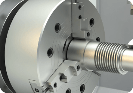
CNC turning on a precision lathe establishes the basic shaft geometry — all diameters, lengths, shoulders, undercuts, and tapers — with a material allowance of 0.1mm to 0.3mm on ground surfaces for subsequent cylindrical grinding. Center holes drilled in both shaft ends at this stage become the reference datum for all subsequent grinding and inspection operations. The accuracy of these center holes — their concentricity, depth, and surface finish — directly determines the accuracy achievable in subsequent grinding, because the shaft rotates on these centers throughout all ground operations. Precision center drilling on a CNC lathe with a live center and careful machine setup is not a trivial operation on a precision motor shaft; it is the foundation on which all subsequent accuracy depends.
Cylindrical grinding is the definitive manufacturing process for precision motor shaft journals and bearing seats. The shaft is mounted between precision centers on the grinding machine and rotated slowly while a high-speed grinding wheel traverses the journal surface, removing 0.002–0.005mm per pass in finishing cuts to achieve the final diameter, roundness, cylindricity, and surface finish. Modern CNC cylindrical grinding machines achieve diameter repeatability of ±0.001mm or better when properly maintained and thermally stabilized, and surface roughness of Ra 0.1–0.4 µm routinely. Post-process gauging — measuring the shaft diameter automatically between grinding passes using an in-process gauge mounted on the machine — eliminates the dimensional variation introduced by thermal expansion and grinding wheel wear, maintaining size consistency across production batches without manual intervention.
Keyways are milled into the shaft before final grinding, to avoid introducing stress concentrations at the keyway edges that could cause micro-cracking during grinding wheel contact. Splines on precision motor shafts are produced by hobbing, milling, or cold rolling — cold-rolled splines have the additional advantage of compressive residual stresses from the rolling process that improve fatigue resistance compared to machined splines. Threads at shaft ends are cut or rolled after final grinding to avoid disturbing the ground surfaces. Thread rolling — pressing the thread form into the shaft surface rather than cutting it — produces stronger threads with compressive surface stresses and is preferred over thread cutting on precision motor shafts where thread fatigue life is a concern.
Understanding how precision motor shafts fail in service — and why — is as important for the designer and specifier as understanding how they are made. Most precision motor shaft failures are traceable to one of a small number of root causes that, once identified, are straightforward to address through design, material selection, or manufacturing process changes.
A complete precision motor shaft specification communicates unambiguously to the manufacturer — whether an internal production facility or an external supplier — exactly what is required and how conformance will be verified. Incomplete specifications are the single most common cause of non-conforming shafts being delivered and accepted, only for the problem to surface during motor assembly or early in service. The following elements must be explicitly defined in any precision motor shaft specification.
Engineers and procurement teams sourcing precision motor shafts face a three-way choice between purchasing standard catalog precision shafts, ordering custom-machined shafts to a specific drawing, or sourcing OEM replacement shafts from motor manufacturers. Each option has a different cost, lead time, and minimum order quantity profile, and the right choice depends on the application's volume requirements, how closely a standard product matches the specification, and whether the shaft is a replacement part or a new design component.
Precision ground shafting — supplied in standard lengths and diameters with guaranteed h6 or g6 diameter tolerance and straightness below 0.02mm per 300mm — is available from shaft and linear motion component suppliers in carbon steel, stainless steel, and case-hardened steel. This option is appropriate when the shaft geometry is simple (constant diameter or stepped with standard increments), the required tolerance matches the catalog product's specification, and secondary operations (keyway milling, threading, drilling) can be performed in-house or by a local machinist. The significant advantage is immediate availability without tooling cost or lead time for custom machining — important for prototyping, repair, and low-volume production.
For motor shaft geometries with specific features — integrated pinion teeth, splines, multiple precision journals at specified runout relationships, tapered ends, or special materials — custom machining from a precision shaft manufacturer is the appropriate route. Custom shafts are produced to the customer's drawing and undergo inspection to the specified acceptance criteria before delivery. Lead times for custom precision motor shafts typically range from 2–6 weeks for standard materials in moderate quantities, with longer lead times for exotic materials, heat treatment sequences with long furnace cycles, or very tight tolerances requiring multiple grind-and-measure iterations. When placing a custom shaft order, providing a complete and unambiguous drawing is the single most important factor in receiving conforming parts on the first delivery — ambiguous drawings generate interpretation errors, requests for clarification that extend lead time, and conforming-to-drawing-but-not-fit-for-purpose shafts that are technically the customer's responsibility.
Not all machine shops that claim to produce precision motor shafts have the equipment, process control, and measurement capability to consistently achieve IT5 or IT6 diameter tolerances, sub-5µm runout, and Ra 0.4 µm surface finish in production. Before qualifying a new precision shaft supplier, verify the following: the grinding machine fleet and its age and maintenance condition; the metrology equipment available for inspection (roundness measurement machine, CMM or precision bench centers with dial gauge, surface profilometer, and their calibration status); the supplier's process documentation and quality management system certification (ISO 9001 as a minimum, IATF 16949 for automotive-supply precision shafts); and their willingness to provide first-article inspection reports (FAIRs) with actual measured values — not just pass/fail stamps — for all critical characteristics on initial samples. A supplier who is reluctant to provide actual measurement data on first articles is telling you something important about how they manage their production quality.
 +86-13861233850